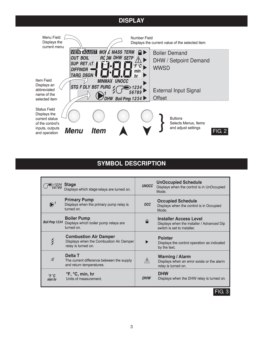
Manuals
/
Lochinvar
/
Household Appliance
/
Water System
Lochinvar
TST2313, MP2 Display, Symbol Description, Boiler Demand DHW / Setpoint Demand WWSD
Models:
TST2313
INS7162
INS7141
MP2
1
3
36
36
Download
36 pages
38.88 Kb
1
2
3
4
5
6
7
8
<
>
Install
Error codes
Boiler Reset Stand Alone
Fire Delay
External Input Signal Offset
Dip Switch Settings
temperature in the building
Testing The Control
Safety
V ac Power
Page 3
Image 3
DISPLAY
Boiler Demand
DHW / Setpoint Demand
WWSD
External Input Signal
Offset
FIG. 2
SYMBOL DESCRIPTION
FIG. 3
3
Page 2
Page 4
Page 3
Image 3
Page 2
Page 4
Contents
INTRODUCTION
ADDITIONAL FUNCTIONS INCLUDE
INSTALLATION INSTRUCTIONS
MENU
TABLE OF CONTENTS
ADJUST
USER INTERFACE
Boiler Demand DHW / Setpoint Demand WWSD
SYMBOL DESCRIPTION
DISPLAY
External Input Signal Offset
SECTION A GENERAL OPERATION
Boiler Reset Stand Alone
DEFINITIONS
SEQUENCE OF OPERATION
Fixed Lead Rotation
Alarm
Boiler Alarm
Combustion Air C. A
Mode
Resetting the Rotation Sequence
Resetting the Running Times
SECTION B STAGING OPERATION
Fire Delay
Fire Delay
Lo / Hi
Lo / Lo
Primary Pump Purge
SECTION C PUMP OPERATION
Fixed Differential
Auto Differential
SECTION D BOILER RESET OPERATION
Boiler Pump Purge
FIG.
temperature in the building
This type of a hydronic radiant floor is embedded in either a thick concrete or gypsumpour. This heating system has a large thermal mass and is slow acting FIG
SECTION E DOMESTIC HOT WATER OPERA- TION
DHW DEMAND
DHW MODE OFF - NO DHW
When a DHW Demand is present, the Relay 9 / DHW con- tact terminals 30 and 31 is closed and the primary pump contact is closed. Priority can only be obtained using exter- nal wiring. During a priority override, the Relay 9 / DHW contact is opened until the heating system has recovered before returning to DHW operation, see Figure 19. This mode can be used if a DHW tank is piped in direct return and a DHW valve is installed
SECTION F SET POINT OPERATION
SETP MODE 3 - Primary Pump during Set Point
SECTION G EXTERNAL INPUT OPERATION
SETP MODE 1 - Setpoint in Parallel
SETP MODE 2 - Set Point in Parallel with Priority
2 - 10 V dc or 4 - 20 mA
0 - 10 V dc or 0 - 20 mA
Boiler Demand
INSTALLATION
115 V ac Power
General
Primary Pump Contact Prim P1
Combustion Air / Alarm Contact C.A./Alarm
Set Point Demand
External Input 0 - 10 V dc
Outdoor Sensor
UnOccupied Switch
Relay 9 / DHW
Boiler Return Sensor
Set Point Demand
External Input
Boiler Demand
DHW Demand
Relay 1 to Relay
Combustion Air or Alarm C.A. / Alarm
Primary Pump Prim P1
Relay 9 / DHW
DIP SWITCH SETTINGS
CLEANING THE CONTROL
GENERAL
Page
Page
Page
This item is only available if the External Input / Stand Alone DIP switch is set to Stand Alone
Boil Mass
Stage Delay
Boiler Minimum
Boiler Maximum
m weather
TESTING THE CONTROL
ERROR MESSAGES
is not a safety limit control
TECHNICAL DATA
TYPICAL BOILER INSTALLATION
TYPICAL BOILER INSTALLATION CONTINUED
Tekmar 150 Controller
TYPICAL DWH PRIORITY HEATING PACKAGE SYSTEM