Manuals
/
Lochinvar
/
Household Appliance
/
Water System
Lochinvar
INS7162, MP2, INS7141, TST2313 Typical DWH Priority Heating Package System
Models:
TST2313
INS7162
INS7141
MP2
1
34
36
36
Download
36 pages
38.88 Kb
29
30
31
32
33
34
35
36
Install
Error codes
Alarm
Fire Delay
Boiler Reset Stand Alone
Cleaning the Control
Testing the Control
Safety
Ac Power
UnOccupied Switch
Page 34
Image 34
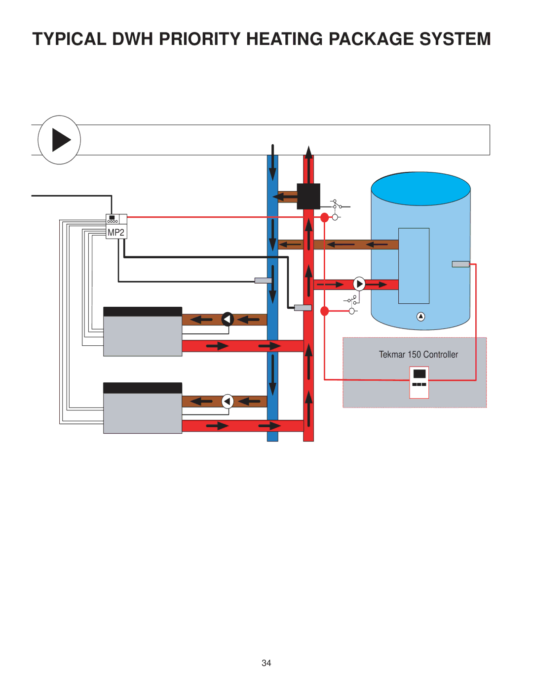
TYPICAL DWH PRIORITY HEATING PACKAGE SYSTEM
MP2
Tekmar 150 Controller
34
Page 33
Page 35
Page 34
Image 34
Page 33
Page 35
Contents
Installation Instructions
Additional Functions Include
Table of Contents
Display
Domestic Hot Water
Boiler Reset Stand Alone
Section a General Operation
Set Point
Combustion Air C. a
Alarm
Boiler Alarm
Fixed Lead Rotation
Section B Staging Operation
Resetting the Rotation Sequence
Resetting the Running Times
Mode
Lo / Hi
Fire Delay
Lo / Lo
Fixed Differential
Section C Pump Operation
Med
Auto Differential
Section D Boiler Reset Operation
Boiler Pump Purge
Type of terminal unit. This improves the control of the air
High Mass Radiant
Section E Domestic HOT Water OPERA- Tion
DHW Demand
DHW Mode 4 DHW in Primary / Secondary with Priority
Section F SET Point Operation
Setp Mode 1 Setpoint in Parallel
Section G External Input Operation
Dc or 0 20 mA
Dc or 4 20 mA
Boiler Demand
Ac Power
General
DHW Demand
External Input 0 10 V dc
Combustion Air / Alarm Contact C.A./Alarm
Set Point Demand
Primary Pump Contact Prim P1
Boiler Return Sensor
UnOccupied Switch
Relay 9 / DHW
Boiler Supply Sensor
External Input
Combustion Air or Alarm C.A. / Alarm
Primary Pump Prim P1
Cleaning the Control
General
Rotate / OFF
Page
Page
Page
Boiler Minimum
Stage Delay
DHW Mode
Boiler Maximum
This item is only available when DHW Mode is set to OFF
Testing the Control
Error Messages
Technical Data
Is not a safety limit control
Typical Boiler Installation
Typical Boiler Installation
Typical DWH Priority Heating Package System
Top
Page
Image
Contents