FIG. 16
HIGH MASS RADIANT (1)
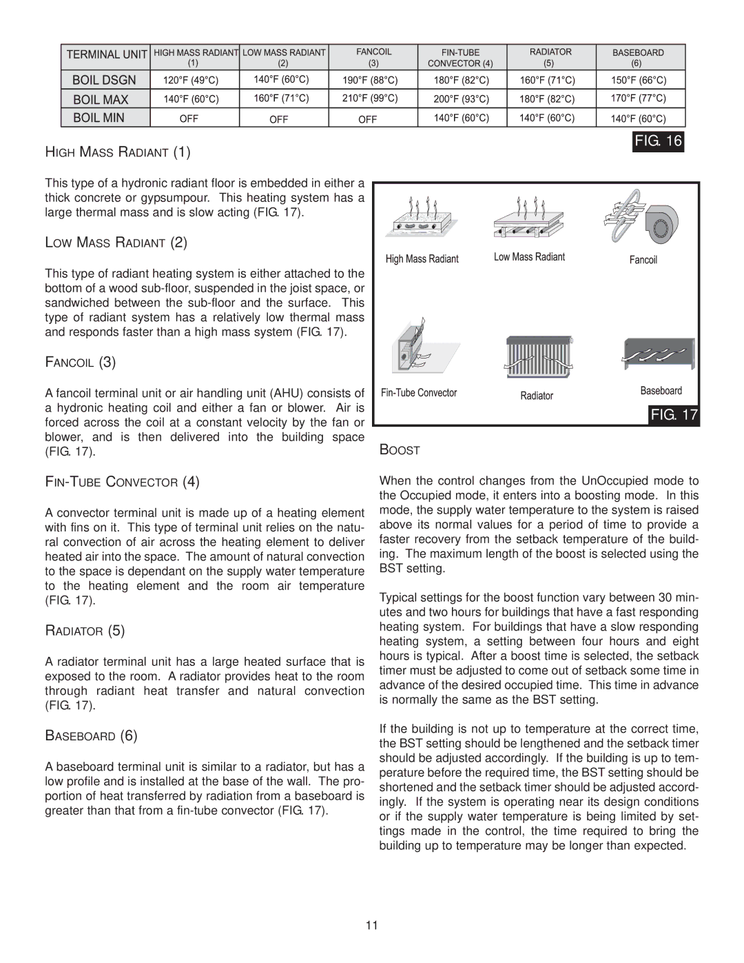
This type of a hydronic radiant floor is embedded in either a thick concrete or gypsumpour. This heating system has a large thermal mass and is slow acting (FIG. 17).
LOW MASS RADIANT (2)
This type of radiant heating system is either attached to the bottom of a wood
FANCOIL (3)
A fancoil terminal unit or air handling unit (AHU) consists of a hydronic heating coil and either a fan or blower. Air is forced across the coil at a constant velocity by the fan or blower, and is then delivered into the building space (FIG. 17).
FIG. 17
BOOST
A convector terminal unit is made up of a heating element with fins on it. This type of terminal unit relies on the natu- ral convection of air across the heating element to deliver heated air into the space. The amount of natural convection to the space is dependant on the supply water temperature to the heating element and the room air temperature (FIG. 17).
RADIATOR (5)
A radiator terminal unit has a large heated surface that is exposed to the room. A radiator provides heat to the room through radiant heat transfer and natural convection (FIG. 17).
BASEBOARD (6)
A baseboard terminal unit is similar to a radiator, but has a low profile and is installed at the base of the wall. The pro- portion of heat transferred by radiation from a baseboard is greater than that from a
11
When the control changes from the UnOccupied mode to the Occupied mode, it enters into a boosting mode. In this mode, the supply water temperature to the system is raised above its normal values for a period of time to provide a faster recovery from the setback temperature of the build- ing. The maximum length of the boost is selected using the BST setting.
Typical settings for the boost function vary between 30 min- utes and two hours for buildings that have a fast responding heating system. For buildings that have a slow responding heating system, a setting between four hours and eight hours is typical. After a boost time is selected, the setback timer must be adjusted to come out of setback some time in advance of the desired occupied time. This time in advance is normally the same as the BST setting.
If the building is not up to temperature at the correct time, the BST setting should be lengthened and the setback timer should be adjusted accordingly. If the building is up to tem- perature before the required time, the BST setting should be shortened and the setback timer should be adjusted accord- ingly. If the system is operating near its design conditions or if the supply water temperature is being limited by set- tings made in the control, the time required to bring the building up to temperature may be longer than expected.