Contents
Channel Multiplex Digital Video Recorder
Copyright Lorex Technologies Inc Alden Road Markham, Ontario
L3R 4C1 Canada
Table of Contents
Page
Important Safety Instructions
Risk of Electric SHOCK. do not Open
Features
Introduction
System Contents
Getting Started
Front Panel Controls
Play
REW / Left
Slow
Camera Select
Back Panel Connections
Accessing the Main Menu
Default Password is
Password, resets system settings, or clears the HDD
Alarm List
Last Record
Full List
Time Search
Timer
Day Start End
Quality IPS
BEST, HIGH, NORMAL, Basic
HDD Overwrite Setup
Record IPS Setup
Record Quality Setup
Alarm REC IPS Setup
Alarm Polarity
Motion Trigger Record
Title
Dwell
Record Method
Motion Detection Setup
1MOTION Detection Setup 1~9
Setting the Internal Audible Alarm Buzzer
Setting the External Audible Alarm Device
Selecting the Audio Input Channel
Setting the Motion Audible Alarm feature
Setting the Alarm Duration
Setting the Dwell Time
Setting the Message Latch Feature
Setting System Time & Date
Changing the System Password
Resetting System to Factory Defaults
Clearing the Hard Drive Data
Operation
Network
On Screen Display OSD
Recording Methods
Viewing Options
Video Search
Playing Back Video
Hardware Connection from DVR Static IP Setting
Software Installation Static IP Setting
Page
Menu Search Timer Record Camera System Event Xnetwork
Connecting the PC and DVR via the Internet
Static IP
Network
Dynamic IP Setting
What is a Dynamic IP ADDRESS?
Software Installation Dynamic IP Setting
Connecting the PC to a Router / Router Login
LAN end
Click
Twice
Page
SVC
Reset Default no
Adsl modem WAN end
Network Server IP
Backup Program Play the last record file
Backup Program
Address Book
Play last record file
Software Operation at the Remote Site
Control Panel and Basic Operation
Video Web Server control panel
Play Back Operation
Digital device control panel
Turbo
Turbo
Advanced Settings
System Config Account Alarm
Reboot
Apply
Mail
FTP
File Path
Tool BOX
Online User
Page
Key Lock
Troubleshooting
Problem Solution
Technical Specifications
TCPIP, ICMP, SMTP, HTTP, FTP
YY/MM/DD, DD/MM/YY, MM/DD/YY, OFF
Cartridge Casing
Remove the Cartridge Casing from the DXR209
Secure the HDD in the Cartridge Casing
Slide the top Cover over the Cartridge Casing
Lock the Cartridge
Appendix 2 Connection Diagram to Cameras and Monitor
Alarm Sensor
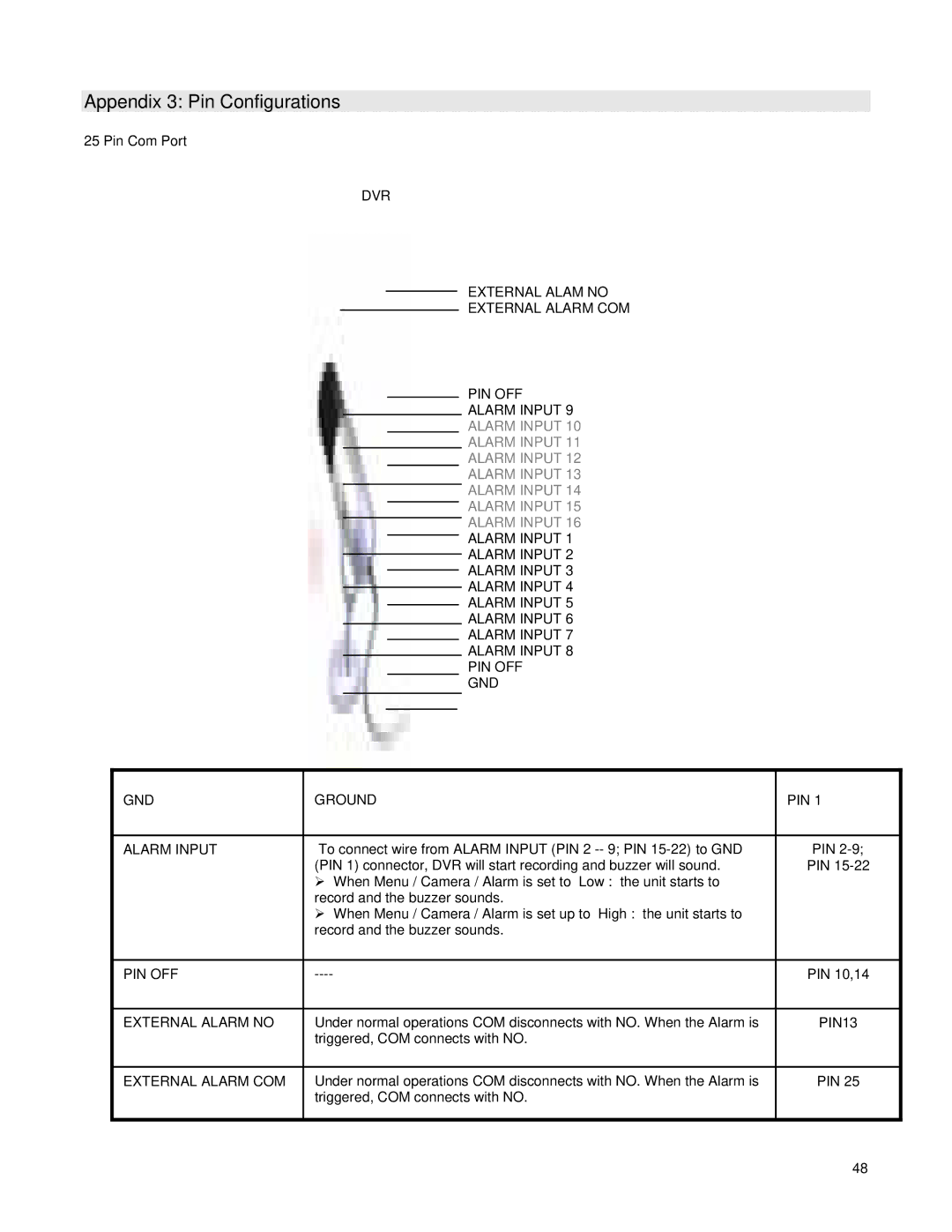
Appendix 3 Pin Configurations
Appendix 4 Rack Mount Installation
Appendix 5 Recording Times in Hours
Ntsc System
Manufacturer Model Capacity Rotation
Appendix 6 Compatible HDD Brands
It’s all on the web