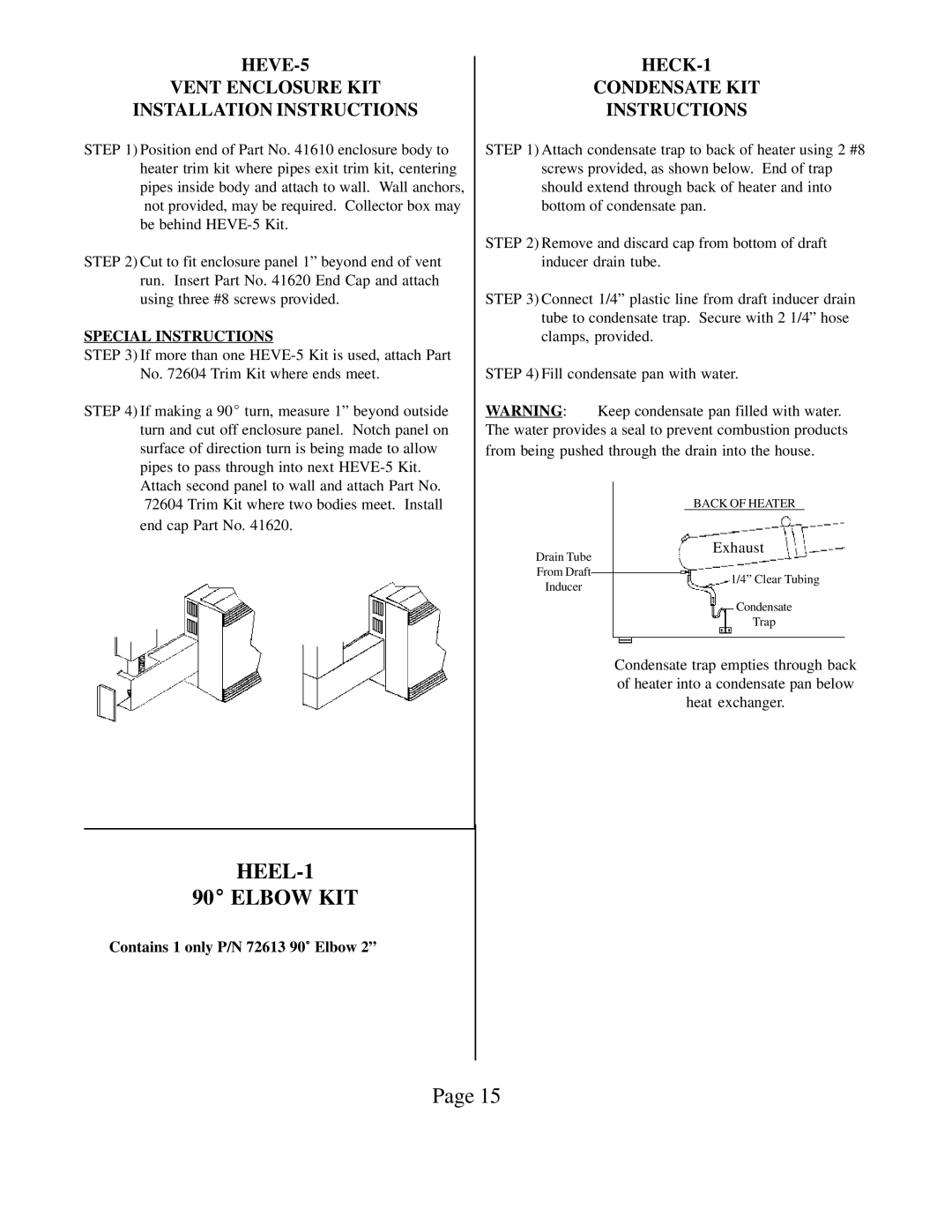
HEDV403, HEDV404 specifications
The Louisville Tin and Stove HEDV403 and HEDV404 are innovative heating solutions designed to combine efficiency, style, and versatility. Both models are part of Louisville Tin and Stove's commitment to quality craftsmanship and modern heating technologies. They offer optimal performance for various home settings, catering to the needs of both traditional and contemporary aesthetics.The HEDV403 model is a prominent choice for those seeking a dependable heating appliance. One of its main features is a robust heating capacity that ensures effective warmth across larger spaces. It utilizes advanced convection heating technology, which allows for even heat distribution while minimizing energy consumption. The sleek design includes a user-friendly digital thermostat, enabling users to easily set and maintain their desired temperature. An integrated fan also enhances airflow, further optimizing heating efficiency.
On the other hand, the HEDV404 model builds on the success of the HEDV403 by introducing additional smart features, making it an ideal choice for tech-savvy homeowners. It boasts Wi-Fi connectivity, allowing users to control and monitor the unit remotely through a smartphone application. This feature is especially beneficial for those who desire convenience and energy management while on the go. Moreover, the HEDV404 includes a more advanced filtration system that helps maintain air quality by removing dust and allergens, promoting a healthier indoor environment.
Both models are constructed with high-quality materials, ensuring durability and longevity. Their stylish appearances make them suitable for a diverse range of interior designs, allowing homeowners to integrate them seamlessly into their living spaces. The contemporary aesthetic is accentuated by sleek lines and modern finishes, appealing to individuals who appreciate design as much as functionality.
Safety is a paramount consideration in both models, which are equipped with multiple safety features such as overheat protection, tip-over switch, and sturdy construction. These attributes offer peace of mind for users, particularly in homes with children or pets.
In summary, the Louisville Tin and Stove HEDV403 and HEDV404 represent the perfect fusion of efficiency, technology, and design. Whether you prefer the straightforward functionality of the HEDV403 or the advanced features of the HEDV404, both models ensure a cozy and inviting atmosphere in any home. Investing in either of these units guarantees not only warmth but also a stylish addition to your living space.

