Strip the wire back about 1/4" inch, insert the wire as far as it will go into the appropriate hole in the supplied
Pin 1 = Ground (Shield) Pin 2 = Hot (+)
Pin 3 = Cold
Connecting the LOGIC I/O
This is a
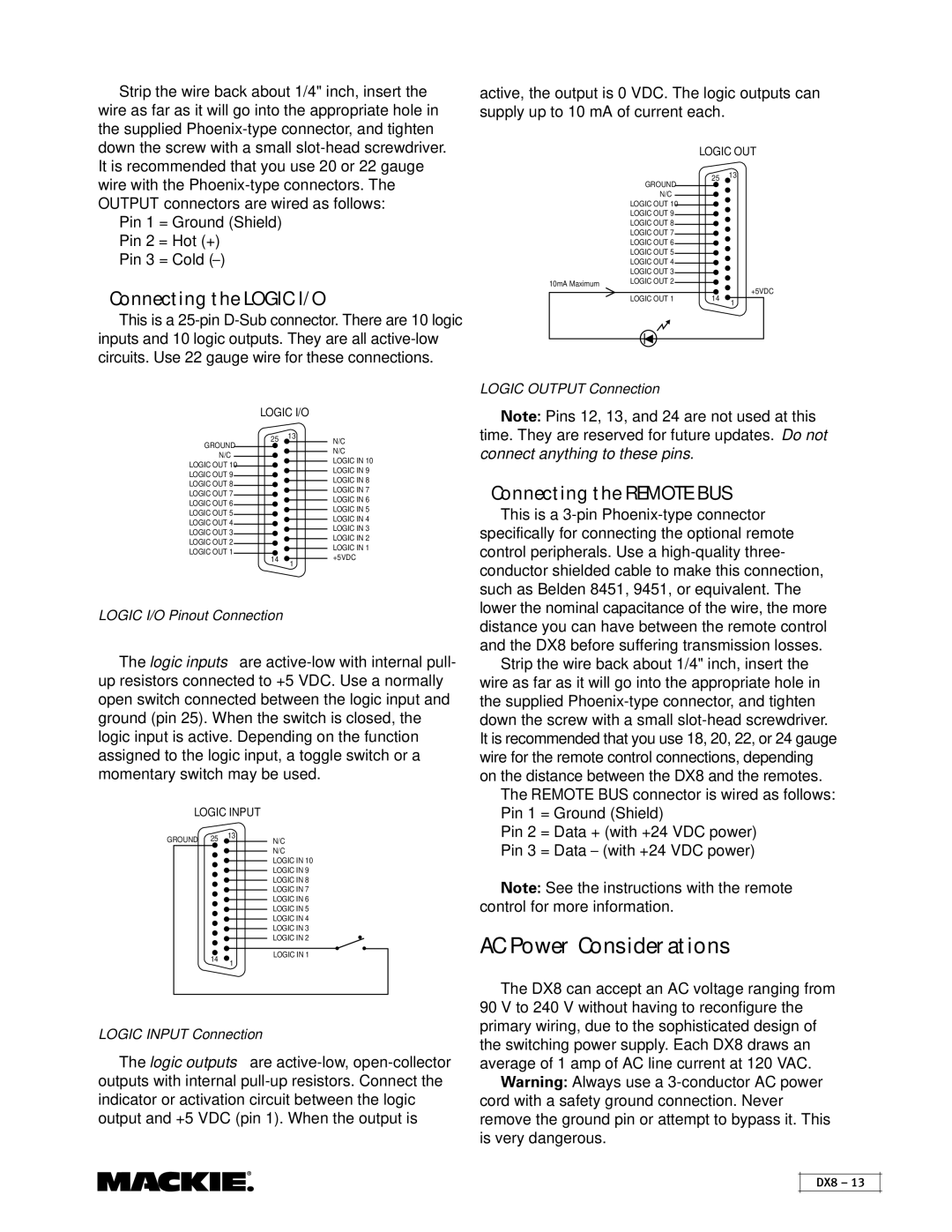
active, the output is 0 VDC. The logic outputs can supply up to 10 mA of current each.
LOGIC OUT
25 13
| GROUND |
| N/C |
| LOGIC OUT 10 |
| LOGIC OUT 9 |
| LOGIC OUT 8 |
| LOGIC OUT 7 |
| LOGIC OUT 6 |
| LOGIC OUT 5 |
| LOGIC OUT 4 |
| LOGIC OUT 3 |
10mA Maximum | LOGIC OUT 2 |
|
LOGIC OUT 1 | 14 | +5VDC | |
1 | |||
|
|
LOGIC OUTPUT Connection
GROUND N/C LOGIC OUT 10
LOGIC OUT 9 LOGIC OUT 8 LOGIC OUT 7 LOGIC OUT 6 LOGIC OUT 5 LOGIC OUT 4 LOGIC OUT 3 LOGIC OUT 2 LOGIC OUT 1
LOGIC I/O
25 | 13 | N/C | |
|
|
| |
|
|
| N/C |
|
|
| |
|
|
| LOGIC IN 10 |
|
|
| |
|
|
| LOGIC IN 9 |
|
|
| |
|
|
| LOGIC IN 8 |
|
|
| |
|
|
| LOGIC IN 7 |
|
|
| |
|
|
| LOGIC IN 6 |
|
|
| |
|
|
| LOGIC IN 5 |
|
|
| |
|
|
| LOGIC IN 4 |
|
|
| |
|
|
| LOGIC IN 3 |
|
|
| |
|
|
| LOGIC IN 2 |
|
|
| |
|
|
| LOGIC IN 1 |
|
|
| |
14+5VDC
1
Note: Pins 12, 13, and 24 are not used at this time. They are reserved for future updates. Do not connect anything to these pins.
Connecting the REMOTE BUS
This is a
LOGIC I/O Pinout Connection
The logic inputs are
LOGIC INPUT
GROUND | 25 | 13 | N/C | |||
| ||||||
|
|
|
|
| N/C | |
|
|
|
|
| ||
|
|
|
|
| LOGIC IN 10 | |
|
|
|
|
| ||
|
|
|
|
| LOGIC IN 9 | |
|
|
|
|
| ||
|
|
|
|
| LOGIC IN 8 | |
|
|
|
|
| ||
|
|
|
|
| LOGIC IN 7 | |
|
|
|
|
| ||
|
|
|
|
| LOGIC IN 6 | |
|
|
|
|
| ||
|
|
|
|
| LOGIC IN 5 | |
|
|
|
|
| ||
|
|
|
|
| LOGIC IN 4 | |
|
|
|
|
| ||
|
|
|
|
| LOGIC IN 3 | |
|
|
|
|
| ||
|
|
|
|
| LOGIC IN 2 | |
|
|
|
|
| ||
|
|
|
|
|
|
|
|
| 14 |
| LOGIC IN 1 | ||
|
| 1 |
|
| ||
|
|
|
|
|
| |
|
|
|
|
|
|
|
LOGIC INPUT Connection
The logic outputs are
distance you can have between the remote control and the DX8 before suffering transmission losses.
Strip the wire back about 1/4" inch, insert the wire as far as it will go into the appropriate hole in the supplied
The REMOTE BUS connector is wired as follows: Pin 1 = Ground (Shield)
Pin 2 = Data + (with +24 VDC power) Pin 3 = Data – (with +24 VDC power)
Note: See the instructions with the remote control for more information.
AC Power Considerations
The DX8 can accept an AC voltage ranging from
90 V to 240 V without having to reconfigure the primary wiring, due to the sophisticated design of the switching power supply. Each DX8 draws an average of 1 amp of AC line current at 120 VAC.
Warning: Always use a
DX8 – 13
