P 4/ 22
 Repair
[4]DISASSEMBLY/ASSEMBLY
[4]-2. Engine and Shaft (cont.)
ASSEMBLING
Assemble by reversing the disassembly procedure.
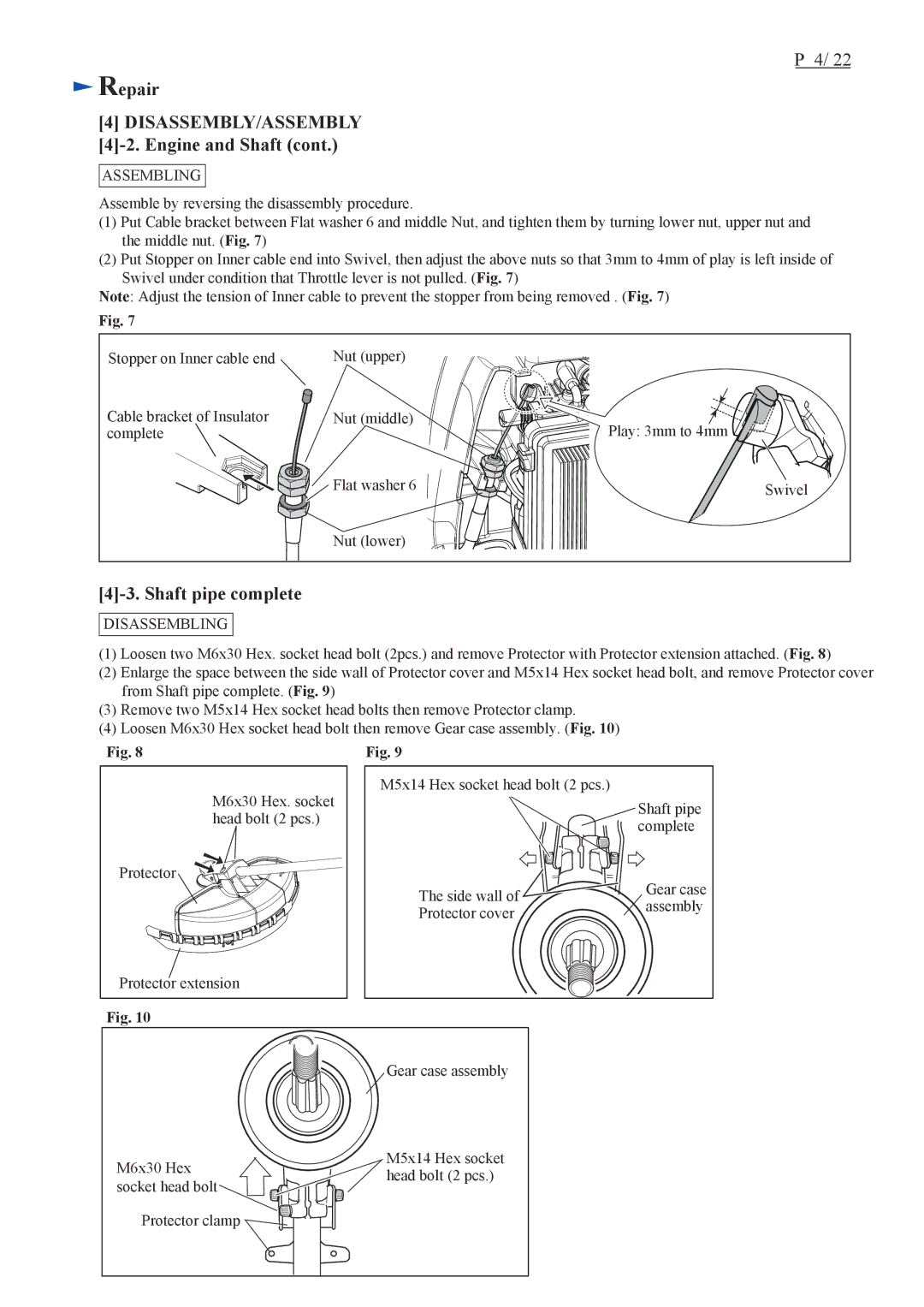
(1)Put Cable bracket between Flat washer 6 and middle Nut, and tighten them by turning lower nut, upper nut and the middle nut. (Fig. 7)
(2)Put Stopper on Inner cable end into Swivel, then adjust the above nuts so that 3mm to 4mm of play is left inside of Swivel under condition that Throttle lever is not pulled. (Fig. 7)
Note: Adjust the tension of Inner cable to prevent the stopper from being removed . (Fig. 7)
Fig. 7
Stopper on Inner cable end | Nut (upper) |
|
Cable bracket of Insulator | Nut (middle) | Play: 3mm to 4mm |
complete |
| |
| Flat washer 6 | Swivel |
| Nut (lower) |
|
[4]-3. Shaft pipe complete
DISASSEMBLING
(1)Loosen two M6x30 Hex. socket head bolt (2pcs.) and remove Protector with Protector extension attached. (Fig. 8)
(2)Enlarge the space between the side wall of Protector cover and M5x14 Hex socket head bolt, and remove Protector cover from Shaft pipe complete. (Fig. 9)
(3)Remove two M5x14 Hex socket head bolts then remove Protector clamp.
(4)Loosen M6x30 Hex socket head bolt then remove Gear case assembly. (Fig. 10)
Fig. 8 | Fig. 9 |
M6x30 Hex. socket |
head bolt (2 pcs.) |
Protector |
Protector extension |
Fig. 10
M5x14 Hex socket head bolt (2 pcs.)
| Shaft pipe | |
| complete | |
The side wall of | Gear case | |
assembly | ||
Protector cover | ||
|
Gear case assembly
M6x30 Hex | M5x14 Hex socket | |
head bolt (2 pcs.) | ||
socket head bolt | ||
| ||
Protector clamp |
|