Repair | P 3/22 |
|
CAUTION: Repair the machine in accordance with “Instruction manual” or “Safety instructions”.
[1] NECESSARY REPAIRING TOOLS
Code No. | Description | Use for |
1R003 | Retaining ring S pliers | Removing Ring spring 19 from Tool holder complete/ Tool holder guide complete |
|
| Removing Retaining ring |
1R004 | Retaining ring S pliers | Removing Ring spring 29 |
1R022 or | Bearing plate (for arbor press) | Removing Ring spring 29 |
1R356 |
|
|
1R032 | Bearing setting plate 8.2 | Assembling Spiral bevel gear 26 |
1R033 | Bearing setting plate 10.2 | Assembling Spiral bevel gear 26 |
1R139 | Drill chuck extractor | Removing Spiral bevel gear 26 |
1R164 | Ring spring setting tool A | Assembling Oil seal 25 to Gear housing complete |
1R165 | Ring spring setting tool B | Assembling Needle bearing complete to Gear housing complete |
1R170 | Removing two M4x25 hex socket head bolts on Inner support complete | |
1R212 | Tip for Retaining ring pliers | Attachment of 1R003 |
1R232 | Pipe 30 | Assembling Oil seal 25 to Gear housing complete |
1R249 | Round bar for arbor | Removing Ring spring 28 |
1R252 | Round bar for arbor | Removing Oil seal 25 from Gear housing complete |
1R269 | Bearing extractor | Removing Ball bearing 608ZZ from Inner support complete |
1R281 | Round bar for arbor | Removing Ring 8 |
1R291 | Retaining ring S and R pliers | Removing Retaining Ring |
1R306 | Ring spring removing jig | Removing Ring spring 29 from Tool holder complete/ Tool holder guide complete |
Piston cylinder | Assembling Ring spring 28 to Tool holder complete/ Tool holder guide complete |
[2] LUBRICATION
Apply the following grease to protect parts and product from unusual abrasion.
*Makita grease RB No.00 to the portions indicated by black triangle
*Molybdenum disulfide lubricant to the portions indicated by gray triangle
Item No. | Description |
|
| Portion to lubricate |
|
|
| Lubricant | Amount | ||||
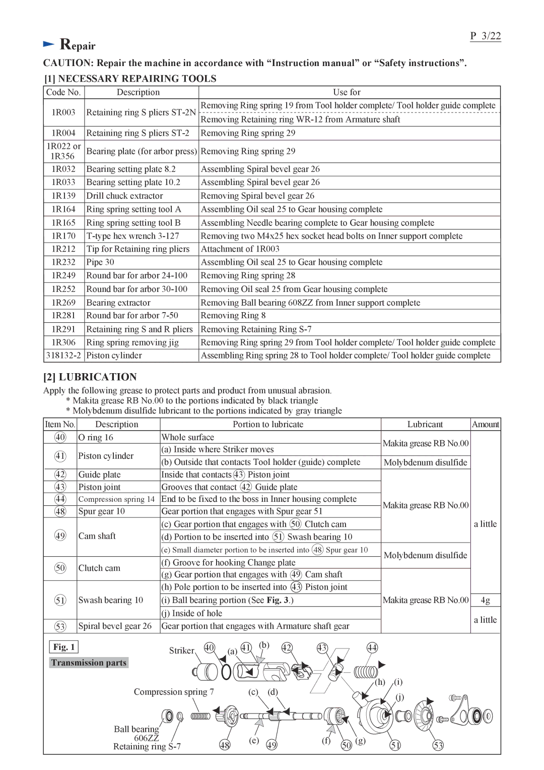
40 | O ring 16 | Whole surface |
|
|
|
|
|
|
| Makita grease RB No.00 |
| ||
|
| (a) Inside where Striker moves |
|
|
|
| |||||||
41 | Piston cylinder |
|
|
|
|
|
| ||||||
(b) Outside that contacts Tool holder (guide) complete |
| Molybdenum disulfide |
| ||||||||||
42 |
|
|
| ||||||||||
Guide plate | Inside that contacts 43 Piston joint |
|
|
|
|
| |||||||
43 | Piston joint | Grooves that contact | 42 Guide plate |
|
|
|
|
| |||||
44 | Compression spring 14 | End to be fixed to the boss in Inner housing complete |
| Makita grease RB No.00 |
| ||||||||
48 | Spur gear 10 | Gear portion that engages with Spur gear 51 |
|
| |||||||||
|
|
|
| ||||||||||
49 | Cam shaft | (c) Gear portion that engages with | 50 | Clutch cam |
|
|
| a little | |||||
(d) Portion to be inserted into | 51 | Swash bearing 10 |
|
|
|
| |||||||
|
| (e) Small diameter portion to be inserted into 48 Spur gear 10 | Molybdenum disulfide |
| |||||||||
|
| (f) Groove for hooking Change plate |
|
|
| ||||||||
50 | Clutch cam |
|
|
|
|
| |||||||
(g) Gear portion that engages with | 49 | Cam shaft |
|
|
|
| |||||||
|
|
|
|
|
| ||||||||
|
| (h) Pole portion to be inserted into | 43 | Piston joint |
|
|
|
| |||||
51 | Swash bearing 10 | (i) Ball bearing portion (See Fig. 3.) |
|
| Makita grease RB No.00 | 4g | |||||||
|
| (j) Inside of hole |
|
|
|
|
|
|
|
| a little | ||
53 | Spiral bevel gear 26 | Gear portion that engages with Armature shaft gear |
|
|
| ||||||||
|
|
|
| ||||||||||
Fig. 1 |
| Striker | 40 | (a) | 41 | (b) | 42 | 43 | 44 |
|
| ||
Transmission parts |
|
|
|
|
|
|
|
|
|
| |||
|
|
|
|
|
|
|
|
|
|
|
| ||
| Compression spring 7 |
| (c) | (d) |
|
|
| (h) (i) |
|
| |||
|
|
|
|
| (j) |
|
| ||||||
|
|
|
|
|
|
|
|
|
|
|
|
| |
| Ball bearing |
|
|
|
|
|
|
|
|
|
|
|
|
| 606ZZ |
|
| 48 | (e) 49 |
| (f) 50 (g) |
| 51 | 53 |
| ||
| Retaining ring |
|
|
|
| ||||||||