P 11/22
 Repair
[3]DISASSEMBLY/ASSEMBLY
DISASSEMBLING
Fig. 26
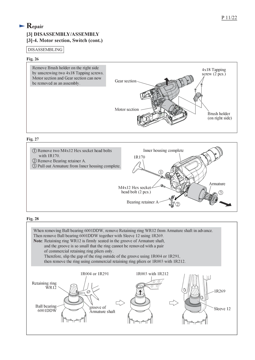
Remove Brush holder on the right side |
| |
by unscrewing two 4x18 Tapping screws. |
| |
Motor section and Gear section can now | Gear section | |
be removed as an assembly. | ||
|
4x18 Tapping screw (2 pcs.)
Motor section ![]()
Brush holder (on right side)
Fig. 27
1Remove two M4x12 Hex socket head bolts with 1R170.
2Remove Bearing retainer A.
3Pull out Armature from Inner housing complete.
Inner housing complete 1R170
1
M4x12 Hex socket | Armature |
| |
head bolt (2 pcs.) | 3 |
Bearing retainer A | 2 |
|
Fig. 28
When removing Ball bearing 6001DDW, remove Retaining ring WR12 from Armature shaft in advance. Then remove Ball bearing 6001DDW together with Sleeve 12 using 1R269.
Note: Retaining ring WR12 is firmly seated in the groove of Armature shaft, and the groove is so small that the ring cannot be removed with a pair of commercial retaining ring pliers only.
Therefore, slip the gap of the ring outside of the groove using 1R004 or 1R291, then remove the ring using commercial retaining ring pliers or 1R003 with 1R212.
| 1R004 or 1R291 | 1R003 with 1R212 | |
Retaining ring |
|
| |
WR12 |
| 1R269 | |
|
| ||
Ball bearing | groove of | Sleeve 12 | |
6001DDW | Armature shaft | ||
|
