Model DV7110 User Guide
For Canadian model
Important Notice For U.S. model
Information to User
Pour le modèle Canadien
Important Safety Instructions
Playing recordable CDs
Features of This Player
Compatible with DVD, Video CD and CD formats
Wide range of DVD viewing options
Easy setup and adjustment using on- screen menus
Line digital progressive-scan component video output
Energy-saving design
How to Proceed in This Manual
Differences in Disc Composition
Table of contents
Preparing the Remote Control
Before Using
Checking Accessories
Inserting batteries into the remote control
Front Panel
Before USING/NAMES and Functions
Names
Rear Panel
Display Window
Remote Control
Functions
Connection Guide
Connecting Your DVD Player
Making Connections
Red
Analog Audio Connection
Audio Connections
Digital Audio Connections
Audio OUT
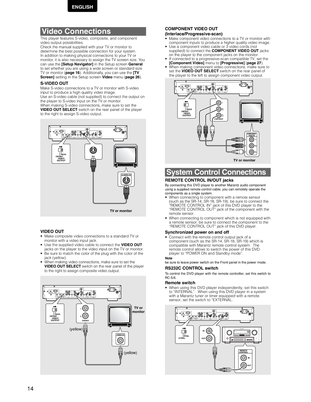
Video OUT
Video Connections
System Control Connections
Using the Setup Navigator
Setting Up the Player
TV System switch
Making Connections Setting UP the Player
Setting the OSD Language On-Screen Display Language
Setting the TV screen size
To exit the Setup screen
Setting compatibility with 96 kHz output
Confirming the settings
To change other player settings in the Setup screen menus
Getting Started Using Your DVD Player
Playing DVDs, Video CDs
When a menu screen is displayed
Chapter Track Skip Forward
Forward and Reverse
Getting Started Using Your DVD PLA YER
Resuming playback from Where you stopped DVD/Video CD
Stopping Playback and Switching Power Off
Adjusting Audio Video Settings
Using the Setup Screen Menus
Color of indicator Disc formats
Changing to the Setup Screen Expert Menu Mode
Setup screen closes
DVD / Video CD
Dolby Digital Out
Settings Dolby Digital Dolby Digital 3 PCM
Settings 96 kHz 3 48 kHz* 96 kHz
DTS Out
Mpeg Out
Settings Mpeg
Factory setting
Digital Out
Differences in screen sizes and DVD formats
Setting the TV Screen Size
Settings 43 Letter Box Pan & Scan Wide
Audio
Connecting to a progressive scan- compatible TV
Settings
Video
Selecting the type of paused image to display
Setting the position of the on-screen display
Selecting Picture Quality Appropriate for Program
Viewing from a Desired Camera Angle Multi-Angle
Turning the angle indicator on and off
Adjusting Audio and Video Settings
Angle
Setting Language Subtitle Preferences Setup Screen Menus
Setting Language Options
Setting the on-screen display OSD language
Selecting an audio language preference
Press Audio repeatedly to select the desired language
Changing Audio Type Video CD/CD
Audio
Press Subtitle repeatedly during playback
Selecting a subtitle language preference
Subtitle
Subtitle and audio language based on
Setting Auto Language to control
Program content
Forcing subtitles to be displayed
Selecting a DVD menu language preference
Selecting subtitles, assist subtitles or no subtitles
Entering the password
Setting the Parental Lock Level
When a DVD with a set Parental Lock level is loaded
Advanced Functions
Changing the Background Color of the Screen
Viewing slow playback
Still Frame/Slow Play/Frame Advance Playback DVD/Video CD
Viewing a still frame
Frame by frame advance playback Viewing one frame at a time
Type of search changes which each press as follows
When performing a time search
Press T/C repeatedly to select the type of search
Memo
Repeat play of a specified section
Repeat play of a chapter/track
Repeat play of a title
Return to a specified location on a disc
Random playback of tracks
Random playback of chapters within one title DVD
Random playback of titles
Random
Stop
Playback in a Desired Order
Programming DVDs
Programming Video CDs, CDs
Additional programming options
Press Program
To save a program in memory DVD
To erase a program saved in memory DVD
Program is saved in memory
Memorizing a Last Memory location to return to later
Resuming playback from where Last Memory was pressed
Continuing Playback from a Specified Location Last
Stop Play
Condition Memory
When a disc that has memorized settings is loaded
Erasing the recorded contents
Press Condition Memory during playback
OSD
When you release the button, the information disappears
Viewing Disc Information
DVD
Video ON/OFF
Resetting the Player to System Settings
Video CD with PBC disabled
CD and Video CD
Additional Information
Disc Care
For Proper and Long Use of This Unit
Language Code List
RS-232C System control
Command list
Example
Troubleshooting
Information
No sound from the Digital OUT optical or coaxial jacks
Digital Out menu is set to Off
Mpeg
Terms
DTS
PCM
Specifications
Français
Compatibilité avec divers formats DVD audionumériques
Particularités de ce lecteur
Compatibilité avec les formats DVD, Video CD et CD
Lecture des disques compacts enregistrables
Choix de l’angle de prise de vues
Grand choix d’options pour le visionnement des DVD
Économie d’énergie
Choix de la langue des dialogues
Comment utiliser ce mode ’emploi
Différences dans le contenu Des disques
Table des matières
Raccordements
Mise en place des piles dans le boîtier de télécommande
Vérification des accessoires
Préparation de la Télécommande
Fonctionnement de la télécommande
Face avant
DES Commandes
Nom et rôle des
Avant D’UTILISER LE Lecteur NOM ET Role
RS232C Control switch Page 15 w RS232C Control Connector
Role DES Commandes
NOM ET
Guide de raccordement
Raccordements
Comment raccorder le Lecteur de DVD
Jaune
Raccordements audio analogiques
Raccordements pour le son
Raccordements audionumériques
Raccordements
Raccordements pour la Commande d’ensemble
Raccordements pour l’image
Commutateur TV System
Raccordement pour Commande RS-232C
Utilisation du navigateur Setup Navigator
Quelques mots sur MOD. Modulation PAL
Choix de la langue d’affichage sur l’écran OSD
Format de l’image sur le téléviseur
Pour quitter la page de mise en oeuvre
Définition de la compatibilité avec la sortie 96 kHz
Validation des réglages
Mise EN Oeuvre DU Lecteur
Déposez un disque dans le tiroir
Utiliser le lecteur de DVD
Lecture des DVD, Video CD Et CD
Appuyez sur la touche Play
Pour écouter un Video CD sans afficher son menu
Si un menu s’affiche
Pour naviguer à travers un menu
Exemple Si le DVD mis en place porte des menus
Saut, dans les deux sens, de chapitre de plage musicale
Examen rapide du disque, dans un sens ou dans l’autre
Appuyez sur la touche Stop
Arrêt de la lecture et mise En veille
Appuyez une fois sur la touche Stop
Retirez le disque
Lors des tout premiers réglages
Utilisation des menus de Configuration
Mise en oeuvre du lecteur
La page de mise en oeuvre s’affiche
Couleur du témoin Type de disque
Adoption du menu de mise en oeuvre Expert
La page de mise en oeuvre se ferme
DVD uniquement
Sortie PCM 96 kHz 96 kHz PCM Out
Sortie Dolby Digital Dolby Digital Out
Sortie DTS DTS Out
Valeurs Dolby Digital Dolby Digital 3 PCM
Sortie Mpeg Mpeg Out
Mise en et hors service de la sortie numérique
Réglage de la dynamique Sonore DVD
Valeurs 43 Letter Box 43 Pan & Scan 169 Wide
Définition du format de l’image sur l’écran du téléviseur
Différences entre formats d’image et gravure sur
Mise
Oeuvre
Valeurs Position-Wide -Normal Off
Choix du type d’image arrêtée
Choix de la position d’affichage sur l’écran
Affichage ou non du témoin d’angle multiple de prise de vues
Pendant la lecture, appuyez sur la touche Angle
Choix de la langue des dialogues
Définition de l’affichage sur ’écran OSD
Choix de la langue d’affichage
French Spanish
Choix de la sortie audio Video CD/CD
Choix de la langue des sous-titres
DES
Choix des langues de base pour les
Dialogues et les sous-titres
Options
Valeurs w/ Subtitle Language English French Spanish
Choix de la langue de travail pour le
Affichage ou non des sous-titres et des sous-titres d’aide
Valeurs With Audio Selected Subtitle
Frappe du mot de passe
Autres fonctions
Définition du niveau de Restriction parentale DVD
Pour déplacer le curseur à l’intérieur du Mot de passe
Appuyez sur la touche Enter pour valider le réglage
Choix de la couleur de fond
Définition du niveau de restriction parentale
Modification du mot de passe
Défilement ralenti
Arrêt sur image, ralenti, avance image par image
Arrêt sur image
Défilement image par image
Mémo
Pour effectuer une recherche par indication d’un temps
Remarques pour la recherche directe
Répétition de la lecture d’un titre
Répétition de la lecture
Répétition de la lecture d’un chapitre d’une plage musicale
Répétition de la lecture d’un passage
Lecture au hasard des titres
Lecture au hasard DVD/Video CD/CD
Lecture au hasard des chapitres d’un titre donné
Lecture au hasard des plages musicales
Programmation de la lecture Lecture programmée
Programmation de la lecture d’un DVD
Pour vérifier le contenu d’un programme
Programmation de la lecture d’un Video CD ou d’un CD
Autres options de programmation
Pour ajouter quelque chose à un programme
Autres Fonctions
Pour sauvegarder un programme grâce à la mémoire DVD
Pour effacer un programme mis en mémoire
Le programme est mis en mémoire
Last Memory
Reprise de la lecture Mémoire de la dernière image
Mise en mémoire de la dernière image
Pour effacer les conditions en mémoire
Pendant la lecture, appuyez sur la touche
Condition Memory
Un jeu de réglages comprend les 6 options volets
Information sur la vitesse de
Sur l’écran, les informations sont superposées à l’image
Quand vous relâchez la touche, l’information disparaît
Transmission
Video CD et CD
Video CD lecture commandée par menu PBC hors service
Réinitialisation du lecteur Aux valeurs système
Pour sortir des informations sur les titres, chapitres et
Prendre soin des disques
Pour utiliser l’appareil correctement et pendant longtemps
Condensation
Évitez LA Chaleur
Produit DE Nettoyage Pour L’OPTIQUE DU Lecteur
Mettez L’APPAREIL Hors Tension Quand Vous NE L’UTILISEZ PAS
Tableau des codes de langue
Commande de système RS 232C
Complementaires
Liste des commandes
Exemple
Guide de dépannage
Le menu Digital Out est réglé sur Off
Glossaire
Caractéristiques techniques
Austria
R.O.M