2 MAINTENANCE
PRESSURE SETTING
DANGER: DO NOT CLIMB ON SIDES OF BALER. USE A LADDER OR WORK PLATFORM WHEN WORKING ON TOP OF THE BALER OR OTHER AREAS OF THE BALER THAT CAN NOT BE REACHED FROM GROUND LEVEL.
WARNING: FEED GATE WILL EXTEND ABOVE THE TOP OF THE BALER WHEN THE FEED GATE IS RAISED.
HYDRAULIC SYSTEM PRESSURE SETTING
1.Using the “MANUAL DOWN” button, run the platen to the fully down position.
2.
3.Relieve any stored hydraulic pressure by pressing in on the solenoid valve pins located on each end of the directional control valve. Use a small blade screwdriver or small allen wrench to perform this operation.
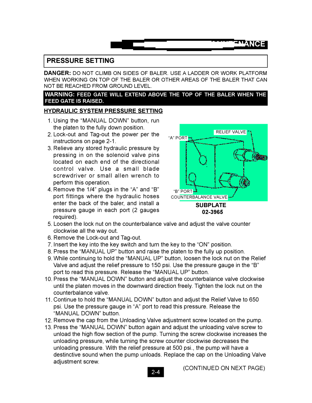
4. Remove the 1/4” plugs in the “A” and “B” port fittings where the hydraulic hoses enter the back of the baler, and install a pressure gauge in each port (2 gauges required).
5.Loosen the lock nut on the counterbalance valve and adjust the valve counter clockwise all the way out.
6.Remove the
7.Insert the key into the key switch and turn the key to the “ON” position.
8.Press the “MANUAL UP” button and raise the platen to the fully up position.
9.While continuing to hold the “MANUAL UP” button, loosen the lock nut on the Relief Valve and adjust the relief pressure to 150 psi. Use the pressure gauge in the “B” port to read this pressure. Release the “MANUAL UP” button.
10.Press the “MANUAL DOWN” button and adjust the counterbalance valve clockwise until the platen moves in the downward direction freely. Tighten the lock nut on the counterbalance valve.
11.Continue to hold the “MANUAL DOWN” button and adjust the Relief Valve to 650 psi. Use the pressure gauge in “A” port to read this pressure. Release the “MANUAL DOWN” button.
12.Remove the cap from the Unloading Valve adjustment screw located on the pump.
13.Press the “MANUAL DOWN” button again and adjust the unloading valve screw to unload the high flow section of the pump. Turning the screw clockwise increases the unloading pressure, while turning the screw counter clockwise decreases the unloading pressure. With the relief pressure at 500 psi., the pump will have a destinctive sound when the pump unloads. Replace the cap on the Unloading Valve adjustment screw.
(CONTINUED ON NEXT PAGE)