Verplaatsbare Heteluchtkanonnen
105398
Portable Forced AIR Heaters
Portable Forced AIR Heaters
Safety Information
Product Identification
Unpacking
Fuels
Tools Needed
Assembly
Ventilation
For B100CEH and B150CEH Models only
To Start Heater
Extension Cord Wire Size Requirements
To Reset Heater
Theory Operation
Storing TRANSPORTING, or Shipping
Preventative Maintenance
Troubleshooting
Heater with Fused or NON-FUSED Ignition Control Assembly
Fault Condition Possible Cause
Heater with NON-FUSED Ignition Control Assembly only
B35CEH and B70CEH Models
Service Procedures
Upper Shell Removal
Fuel Filter
Ignitor
Disconnecting Ignitor Wires from Ignition Control Assembly
AIR OUTPUT, AIR INTAKE, and Lint Filters
Pump Pressure Adjustment
Placement and Proper Routing
Nozzle Assembly
Fuel and AIR Line Replacement Proper Routing
Assembly. See Fuel and Airline Re
Pump Rotor
Procedure if Rotor is Binding
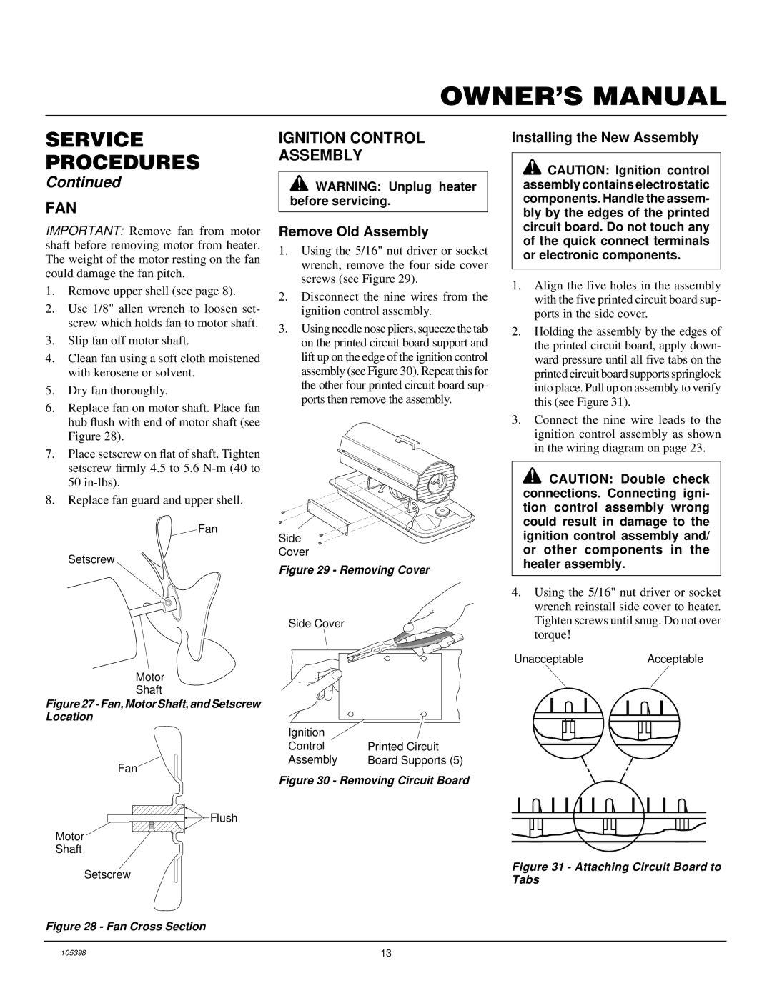
FAN
Ignition Control Assembly
Remove Old Assembly
Installing the New Assembly
Motor and Pump Assembly
Illustrated Parts Breakdown
B35CEH Model
Parts Available not Shown
Parts List
KEY Part
Number Description QTY
B70CEH Model
FHPF3-5C
B100CEH Model
KEY Part Number Description QTY
B150CEH Model
Desired part
B150CEH Model
B100CEH and B150CEH Models
Wheels Handles
Specifications
Wiring Diagram
1425 2850
Heavy Duty Wheels and Handle KIT HA1202
Accessories
Ignition Control ASSEMBLY/PHOTOCELL Tester HA1170
AIR Gauge KIT HA1180
EC Conformity Declaration
EC Conformity Declaration
Certificate of General Equipment Limited ONE Year Warranty
Warranty Service
Corporate Headquarters
Appareils DE Chauffage Individuels À AIR Forcé
Appareils DE Chauffage Individuels À AIR Forcé LA Sécurité
Avertissements
Alimentation en carburant
Avertissement Ne se ser
Manuel D’UTILISATION Nomenclature DES Pièces
Déballage
Carburants
Appareils DE Chauffage Individuels À AIR Forcé Montage
Pour Modè LES B100CEH ET B150CEH
Outils Né cessaires
Fonctionnement
Manuel D’UTILISATION Principes DE Fonctionnement
Lemé nt Pé riodicité Opé ration
Tableau
’ENTRETIEN
Préventif
Manuel D’UTILISATION Dépannage
Anomalie Observé E Cause Probable Remè DE
Avertissement Haute tension
Appareils DE Chauffage Individuels À AIR Forcé Dépannage
On et le radiateur ne fonctionne pas
Remis à l’état initial
Modè les B35CEH et B70CEH
Manuel D’UTILISATION Procédures ’ENTRETIEN
DÉ Pose DU Couvercle
Filtre À Carburant
Cellule photoélectrique
Allumeur
RÉ Glage DE LA Pression DE LA Pompe
Filtres DE Sortie D’AIR, D’ENTRÉ E D’AIR ET À Peluche
Conduites de combustible et d’air
Gicleur
Rotor DE LA Pompe
Procé dure en cas de grippage
Déposer le cache-filtre et les filtres à air
Dé pose des piè ces existantes
Commande D’ALLUMAGE
Installation des piè ces neuves
Ventilateur
Schémas Électriques
Manuel D’UTILISATION Spécifications
Appareils DE Chauffage Individuels À AIR Forcé VUE Éclatée
Modè LE B35CEH
Ensemble moteur et pompe
PIÈ CES Disponibles NON Illustré ES
Manuel D’UTILISATION Liste DES Pièces
˚ DE Numé RO RÉ F DU PIÈ CE Designation
RÉ F DU PIÈ CE Designation QTÉ
Modè LE B70CEH
RÉ F DU PIÈ CE Designation
Ensemble moteur et pompe
Modè LE B100CEH
˚ DE Numé RO RÉ F DU PIÈ CE Designation QTÉ
Modè LE B150CEH
Vis, #10-32 x 3/4 M50400
JEU DE Roues ET Poigné ES Standard HA1206
Modè LES B100CEH ET B150CEH
JEU DE Manomè TRE
JEU DE Roues ET Poigné E Pour Usage Intensif HA1202
DÉ Claration DE Conformité À LA CE
Manuel D’UTILISATION Déclaration DE Conformité À LA CE
Garantie ET Réparations
Services Fournis AU Titre DE LA Garantie
Verplaatsbare Hetelucht Kanonnen
VEILIGHEIDSIN- Formatie
Waarschuwing
Bijvullen
Produkt Identifikatie
Uitpakken
Brandstoffen
Ventilatie
Alleen Voor Modellen B100CEH EN B150CEH
Benodigd gereedschap
Bediening
Overzicht VAN DE Werking
OPSLAG, Vervoer of Verzending
Preventief Onderhoud
Onderdeel Wanneer? Onderhoud
Waarschuwing Hoogspanning
Problemen Oplossen
Verwarmer MET Ontstekingsmechanisme MET of Zonder Zekering
Probleem Mogelijke Oorzaak Oplossing
De ontsteker zie pagina
Als u geen problemen vindt, vervang dan
Verwarmer MET Ontstekingsmechanisme Zonder Zekering
Probleem Mogelijke Oorzaak
Modellen B35CEH en B70CEH
ONDERHOUDS- Procedures
DE Behuizing Verwijderen
Brandstoffilter
Ontsteker
HET LUCHTUITLAAT-, LUCHTINLAAT- EN LINT- Filter
DE Pompdruk Bijstellen
Model Pompdruk
Bevestig sproeier op branderbeugel
Sproeier
Pomprotor
Procedure voor klemmende pomprotor
Oud ontstekingsmechanisme verwijderen
Nieum mechanisme installeren
Ventilator
Ontstekingsmechanisme
Technische Gegevens
BEDRADINGSSCHEMA’S
Illustraties EN Lijst VAN Onderdelen
B35CEH
Motor en pomp
Lijst VAN Onderdelen
NUM Onderdeel AAN MER Nummer Omschrijving TAL
Onderdelen Leverbaar Niet Afgebeeld
B70CEH
FHPF3-5C
B100CEH
Sluitring, nr 10-11 M27694 Stelschroef
10-11
098511-257 Bovenste deel behuizing
Testapparaat Voor
Verrijdbare Onder Accessoires Stellen EN Hendels
Manometerset HA1180
Standaard Onderstel EN Hendel HA1206
Conformiteitsverklaring Voor DE EU
Conformiteits Verklaring Voor DE EU
Garantieservice
Garantie EN Reparatieservice
Tragbare Hochdruck Heissluftturbinen
SICHERHEITS- Informationen
Warnhinweise
Behälter aufweisen
Das Heizgerät aus dem Versandkarton entnehmen
PRODUKT- Beschreibung
Auspacken
Kraftstoffe
Nö tiges Werkzeug
Zusammenbau
Entlüftung
NUR FÜ R B100CEH UND B150CEH Modelle
Abschalten DES Heizgerä TES
Arbeitsweise Bedienung
Einschalten DES Heizgerä TS
Verlä Ngerungskabeln
Siehe Lagerung, Transport oder
Lagerung Transport Versand
Regelmässige Wartung
Teil Hä ufigkeit Durchfü hrung
Rung, Transport, Versand auf Seite
Fehlersuche
Beobachteter Fehler MÖ Gliche Ursache Abhilfe
Achtung Hochspannung
Nicht auf, wenn der Schalter eingeschaltet
Heizung NUR MIT Nicht Gesicherter ZÜ Ndsteuerung
B35CEH und B70CEH Modelle
Wartungs Verfahren
Entfernen DES Oberen Gehä Uses
Kraftstoffilter
ZÜ Nder
LUFTAUSLASS-,LUFTEINLASS- UND Staubfilter
Pumpendruckein Stellung
DÜ Senbaugruppe
Verfahren, wenn die Pumpe festgefressen ist
Pumpenrotor
Neue Baugruppe montieren
LÜ Fter
ZÜ Ndstromanlage
Alte Baugruppe entfernen
Schaltplan
Technische Daten
BEBILDERTE4 Ersatzteilliste
B35CEH Modell
Motor- und Pumpenbaugruppe
Erhä Ltliche Teile Nicht Gezeigt
ERSATZTEIL- Katalog
Kenn Teilnummer Beschreibung
Teilnummer Beschreibung STÜ CK
B70CEH Modell
Bebilderte Ersatzteilliste
102861-01 Nylongegenmutter 12-1 102001-23 Motor 102349-01
B100CEH Modell
Kenn Teilnummer Beschreibung STÜ CK
B150CEH Modell
BEBILDERTE2 Ersatzteilliste
098511-257 Oberes Gehäuse
Satz Standardrä DER UND
Räder UND Zusatzgeräte Handgriffe
B100CEH UND B150CEH Modelle
Luftdruckmesser HA1180
EU-KONFORMITÄ Tserklä Rung
EU-ÜBEREINSTIMMUNGSERKLÄRUNG
Garantieleistungen
Garantie UND Reparaturdienst
105398
Not a UPC