Replacement Parts List
Note: Important Safety Notice
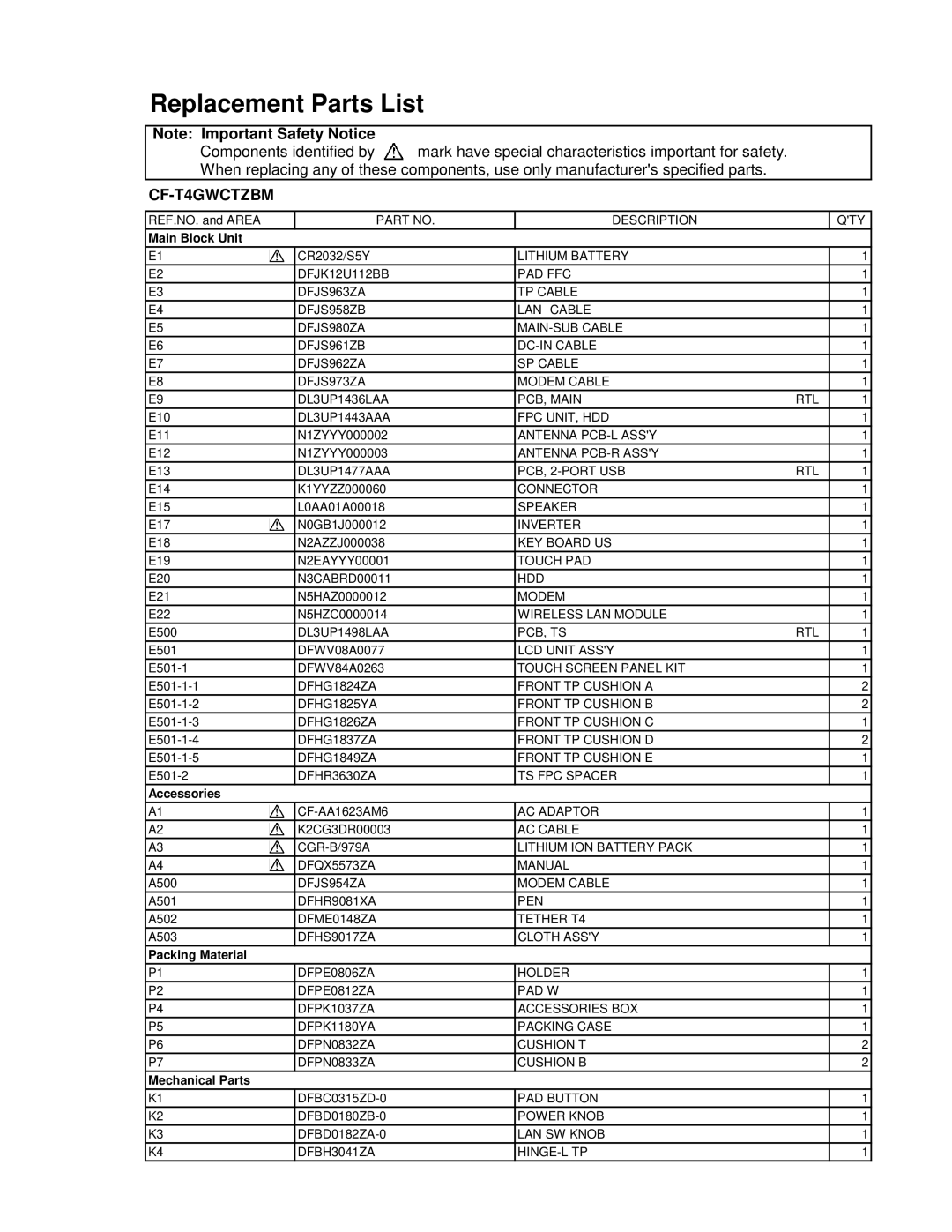
Components identified by ![]() mark have special characteristics important for safety. When replacing any of these components, use only manufacturer's specified parts.
mark have special characteristics important for safety. When replacing any of these components, use only manufacturer's specified parts.
CF-T4GWCTZBM
REF.NO. and AREA | PART NO. | DESCRIPTION |
|
|
|
Main Block Unit
Q'TY
E1 |
|
| CR2032/S5Y | LITHIUM BATTERY |
|
|
|
| |||
E2 | DFJK12U112BB | PAD FFC |
| ||
E3 | DFJS963ZA | TP CABLE |
| ||
E4 | DFJS958ZB | LAN CABLE |
| ||
E5 | DFJS980ZA |
| |||
E6 | DFJS961ZB |
| |||
E7 | DFJS962ZA | SP CABLE |
| ||
E8 | DFJS973ZA | MODEM CABLE |
| ||
E9 | DL3UP1436LAA | PCB, MAIN | RTL | ||
E10 | DL3UP1443AAA | FPC UNIT, HDD |
| ||
E11 | N1ZYYY000002 | ANTENNA |
| ||
E12 | N1ZYYY000003 | ANTENNA |
| ||
E13 | DL3UP1477AAA | PCB, | RTL | ||
E14 | K1YYZZ000060 | CONNECTOR |
| ||
E15 | L0AA01A00018 | SPEAKER |
| ||
E17 |
|
| N0GB1J000012 | INVERTER |
|
|
| ||||
E18 | N2AZZJ000038 | KEY BOARD US |
| ||
E19 | N2EAYYY00001 | TOUCH PAD |
| ||
E20 | N3CABRD00011 | HDD |
| ||
E21 | N5HAZ0000012 | MODEM |
| ||
E22 | N5HZC0000014 | WIRELESS LAN MODULE |
| ||
E500 | DL3UP1498LAA | PCB, TS | RTL | ||
E501 | DFWV08A0077 | LCD UNIT ASS'Y |
| ||
DFWV84A0263 | TOUCH SCREEN PANEL KIT |
| |||
DFHG1824ZA | FRONT TP CUSHION A |
| |||
DFHG1825YA | FRONT TP CUSHION B |
| |||
DFHG1826ZA | FRONT TP CUSHION C |
| |||
DFHG1837ZA | FRONT TP CUSHION D |
| |||
DFHG1849ZA | FRONT TP CUSHION E |
| |||
DFHR3630ZA | TS FPC SPACER |
| |||
Accessories |
|
|
| ||
1
1
1
1
1
1
1
1
1
1
1
1
1
1
1
1
1
1
1
1
1
1
1
1
2
2
1
2
1
1
A1 |
|
| AC ADAPTOR | |
|
| |||
A2 |
|
| K2CG3DR00003 | AC CABLE |
| ||||
A3 |
|
| LITHIUM ION BATTERY PACK | |
| ||||
A4 |
|
| DFQX5573ZA | MANUAL |
| ||||
A500 | DFJS954ZA | MODEM CABLE | ||
A501 | DFHR9081XA | PEN | ||
A502 | DFME0148ZA | TETHER T4 | ||
A503 | DFHS9017ZA | CLOTH ASS'Y | ||
Packing Material |
|
| ||
P1 | DFPE0806ZA | HOLDER | ||
P2 | DFPE0812ZA | PAD W | ||
P4 | DFPK1037ZA | ACCESSORIES BOX | ||
P5 | DFPK1180YA | PACKING CASE | ||
P6 | DFPN0832ZA | CUSHION T | ||
P7 | DFPN0833ZA | CUSHION B | ||
Mechanical Parts |
|
| ||
K1 | PAD BUTTON | |||
K2 | POWER KNOB | |||
K3 | LAN SW KNOB | |||
K4 | DFBH3041ZA |
| ||
|
|
|
|
|
1
1
1
1
1
1
1
1
1
1
1
1
2
2
1
1
1
1