Contents
CF-T4
Page
Page
Page
Page
Page
Page
Connection Diagram
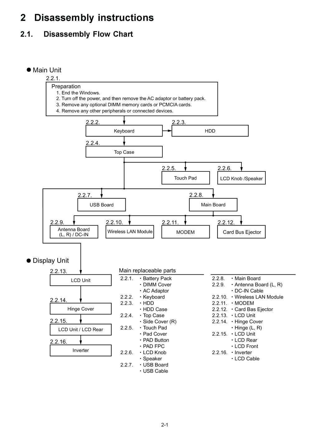
Disassembly Flow Chart
Disassembly instructions
Disassembly
Preparation
Removing the Keyboard
Removing the Top Case
Removing the HDD
HDD
HDD FFC
PAD FFC
Removing the Touch Pad
Removing the LCD Knob and the Speaker
Removing the Main Board
Removing the USB Board
Removing the Antenna Board L,R and the DC-IN Cable
Removing the Wireless LAN Module
DC-IN
LAN
Removing the Card Bus Ejector
Removing the Modem
Removing the LCD Unit and the LCD Rear
Removing the LCD Unit
Removing the Hinge Cover
Remove the Inverter
Reassenbly instructions
Assembly knowhow of part LCD
Rear Damper
Putting of conductive cloth of LCD cable 75 5mm
Assembly of Touch Pad
Installation and Line processing of Speaker
Processing of DC-IN Cable and Coaxial Cable
Obtaining of Side Cover L
Processing of Modem Cable and LAN Cable
Processing of USB Cable
Screw tightening procedure of Each Unit
ScrewB ScrewC ScrewB
Display Section
Exploded View
LCD Unit Assy / Pen Holder Section
Cabinet Section
JK2
Bottom Section
Replacement Parts List
DFBH3042ZA HINGE-R TP
DFMY3192ZA Heat Spreader Bottom
EEFCD0D151ER
Replacement Parts List
Page
Page
Page
Page
EEFUD0D331ER
EEFCD0D101ER
EEFSX0D271ER
EEFUD0E221ER
DCUM1A1051BD
ERJ2GEJ103X RESISTOR, 1/16W, 10KΩ
ECJ2FF1A106Z
EEFUD0J101ER
EEFUD0G151ER
Connector
Thermistor
Diode
FUSE, 2A
DEDRB081L20 Diode
FUSE, 1A
IC, CPU
IC, Clock Generator
IC, USB Power Control
IC, PC-CARD SW
IC, Regulator
Inductor
IC, Liner
Inductor DDB5Z024E-L
Inductor DDB5Z024C-L DDB5Z032A-L DDB5Z021C-Y
Transistor
Poly SW
Transistor ERJ2GEJ681X
B1GFCFEN0003 Transistor DETA144EETL
ERJ2RKF27R4X
ERJ2GEJ151X
ERJ2GEJ750X
ERJ3GEYJ100V
ERJ2RKF2210X
ERJ2RKF1000X
ERJ2GEJ103X RESISTOR, 1/16W
ERJ2RKF80R6X RESISTOR, 1/16W
ERJ2GEJ222X
ERJ2RKF1002X RESISTOR, 1/16W, 10KΩ ERJ2RKF75R0X
ERJ2GEJ101X
Resistor Array ERJ2RKF1501X
ERJ2GEJ390X
ERJ2GEJ220X
ERJ2GEJ102X RESISTOR, 1/16W, 1KΩ
ERJ3GEYJ2R2V
ERJ2GEJ120X
ERJ2RKF49R9X
ERJ2GEJ330X
ERJ2RKF4750X
ERJ2GEJ203X RESISTOR, 1/16W, 20KΩ
ERJ2RKF22R6X
ERJ2GEJ106X RESISTOR, 1/16W, 10MΩ
ERJ2GEJ105X RESISTOR, 1/16W, 1MΩ
Filter
ERJ2GEJ473X RESISTOR, 1/16W, 47KΩ
ERJ2GEJ472X
ERJ2GEJ100X
ERJ2RKF3901X
ERJ2GEJ471X
ERJ2RHD103X RESISTOR, 1/16W, 10KΩ
ERJ2GEJ561X
ERJ2RKF1003X
ERJ2RHD333X RESISTOR, 1/16W, 33KΩ
ERJ2RHD222X
ERJ2RKF5102X RESISTOR, 1/16W, 51KΩ
Trance
DRHM0100ZA Spacer DRHM0099ZA
EEFUD0J151ER
DEARA8AJ473M Resistor Array
ERJ2GEJ822X
ERJ2GEJ270X
ERJ2GEJ152X

 Main Unit
 Display Unit