CF-W4
Page
Page
Laser Safety Information
Page
Page
Page
Handling
Connection Diagram
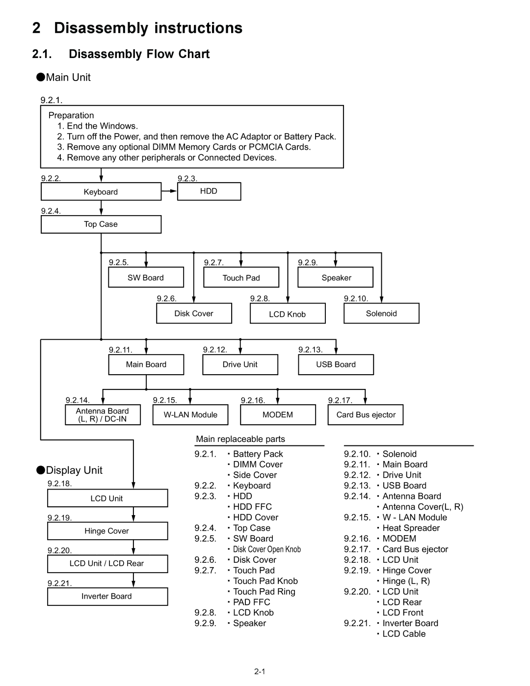
Disassembly instructions
Disassembly Flow Chart
Preparation
Disassembly
Remove the Keyboard
HDD
Remove the HDD
Remove the Top Case
HDD FFC
Remove the SW Board
FFC PAD FFC SW
Remove the Touch Pad
Remove the Disc Cover
PAD FFC
Remove the Solenoid
Remove the LCD Knob
Remove the Speaker
Remove the Main Board
CN3
Remove the Antenna BoardL,R
Remove the Wireless LAN Module
Remove the Drive Unit
Remove the USB Board
Remove the Card Bus Ejector
Remove the Modem
Modem
Remove the Hinge Cover
Remove the LCD Unit
Remove the LCD Unit and the LCD Rear
Remove the Inverter Board
Reassembly instructions
Assembly knowhow of part LCD
LCD Cable Inverter part
Page
Assembly of Brake Lever
Brake Lever completion chart
Switch Board assembly specification
Solenoid Wire Rod processing
Speaker installation and Line processing
Assembly of Antenna Board Part
Speaker installation Processing of Speaker Cable
PET
Modem Cable, Rib and LAN Cable processing
LAN
Wire Rod processing of Lithium Battery
USB Cable processing
Affixation of HDD Gasket
Assembly of Disk Cover
Assembly of Disk Cover
Assembly of Touch Pad
Screw tightening procedure of each unit
Screw E Screw B Screw C Screw D Screw H Screw F
Specification of affixation of PET tape to Heat Spreader
Exploded View
Display Section
Cabinet Section
Bottom Section
JK2
Replacement Parts List
PAD Cover Ring
DFMD4057ZA KB Hook F999
DXQT2+E6FNL Screw
Replacement Parts List
EEFCD0D151ER
Page
Page
Page
Page
Page
EEFCD0D101ER
EEFUD0D331ER
EEFSX0D271ER
EEFUD0E221ER
Page
ECJ2FF1A106Z
ERJ2GEJ103X RESISTOR, 1/16W, 10KΩ
EEFUD0G151ER
Connector
EEFUD0J101ER
Thermistor
Diode
IC, CPU
DEDRB081L20 Diode
FUSE, 2A
IC, Chip SET
IC, Logic
IC, USB Power Control
IC, FET Switch
IC, Cardbus Control
DDB5Z028C-L Inductor
Inductor DDB5Z024E-L
Inductor DDB5Z024C-L DDB5Z021C-Y
DDAZS100MT3T Inductor
B1GFCFEN0003 Transistor DETA144EETL
ERJ2GEJ151X
Transistor ERJ2GEJ681X
ERJ2RKF27R4X
ERJ2RKF54R9X
ERJ2RKF2210X
ERJ2RKF2001X RESISTOR, 1/16W, 2KΩ ERJ2GEJ562X
ERJ2GEJ750X
ERJ2RKF1000X
ERJ2RKF80R6X RESISTOR, 1/16W
ERJ2GEJ103X RESISTOR, 1/16W
ERJ2GEJ222X
Resistor Array ERJ2RKF1501X
ERJ2GEJ101X
ERJ2RKF1002X RESISTOR, 1/16W, 10KΩ ERJ2RKF75R0X
ERJ2GEJ390X
ERJ2GEJ102X RESISTOR, 1/16W, 1KΩ
ERJ2GEJ220X
ERJ3GEYJ2R2V
ERJ2GEJ330X
ERJ2RKF49R9X
ERJ2GEJ120X
ERJ2RKF4750X
ERJ2GEJ106X RESISTOR, 1/16W, 10MΩ
ERJ2RKF22R6X
ERJ2GEJ203X RESISTOR, 1/16W, 20KΩ
ERJ2GEJ105X RESISTOR, 1/16W, 1MΩ
ERJ2GEJ473X RESISTOR, 1/16W, 47KΩ
ERJ3GEYJ121V
DEARA8AJ103M Resistor Array
Filter
ERJ2GEJ333X RESISTOR, 1/16W, 33KΩ
ERJ2GEJ334X
EXBV8V750JV Resistor Array
ERJ2GEJ363X RESISTOR, 1/16W, 36KΩ
ERA3YEB103V RESISTOR, 1/16W, 10KΩ
ERA3YKB104V
ERA3YEB203V RESISTOR, 1/16W, 20KΩ
ERA3YEB303V RESISTOR, 1/16W, 30KΩ
ERJ2RKF1102X RESISTOR, 1/16W, 11KΩ
ERA3YEB333V RESISTOR, 1/16W, 33KΩ
ERJ2RHD132X
ERJ2RKF1302X RESISTOR, 1/16W, 13KΩ
SW 952 SW K0D113B00081 K0L1BA000115

 Main Unit
 Display Unit