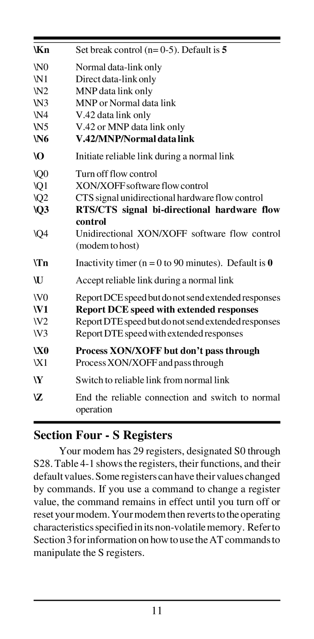
\Kn | Set break control (n= |
\N0 | Normal |
\N1 | Direct |
\N2 | MNP data link only |
\N3 | MNP or Normal data link |
\N4 | V.42 data link only |
\N5 | V.42 or MNP data link only |
\N6 | V.42/MNP/Normal data link |
\O | Initiate reliable link during a normal link |
\Q0 | Turn off flow control |
\Q1 | XON/XOFF software flow control |
\Q2 | CTS signal unidirectional hardware flow control |
\Q3 | RTS/CTS signal |
| control |
\Q4 | Unidirectional XON/XOFF software flow control |
| (modem to host) |
\Tn | Inactivity timer (n = 0 to 90 minutes). Default is 0 |
\U | Accept reliable link during a normal link |
\V0 | Report DCE speed but do not send extended responses |
\V1 | Report DCE speed with extended responses |
\V2 | Report DTE speed but do not send extended responses |
\V3 | Report DTE speed with extended responses |
\X0 | Process XON/XOFF but don’t pass through |
\X1 | Process XON/XOFF and pass through |
\Y | Switch to reliable link from normal link |
\Z | End the reliable connection and switch to normal |
| operation |
|
|
Section Four - S Registers
Your modem has 29 registers, designated S0 through S28. Table
11