Installation
Procedure
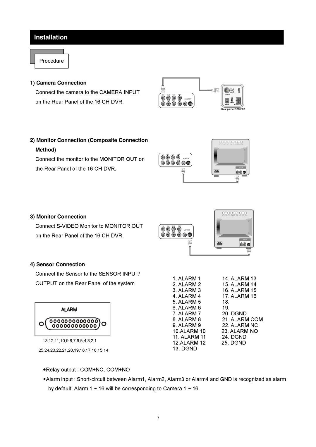
1) Camera Connection
Connect the camera to the CAMERA INPUT on the Rear Panel of the 16 CH DVR.
CH1 CH2 CH3 CH4
MONITOR
CH1 CH2 CH3 CH4
DC |
LEVEL |
V.P |
VIDEO |
| DC |
| VIDEO |
LENS | AC24V/DC12 |
Rear part of CAMERA
2)Monitor Connection (Composite Connection Method)
Connect the monitor to the MONITOR OUT on the Rear Panel of the 16 CH DVR.
3)Monitor Connection
Connect
4) Sensor Connection
Connect the Sensor to the SENSOR INPUT/ OUTPUT on the Rear Panel of the system
13,12,11,10,9,8,7,6,5,4,3,2,1
25,24,23,22,21,20,19,18,17,16,15,14
CH1 CH2 CH3 CH4
MONITOR
CH1 CH2 CH3 CH4
VIDEO A
IN OUT
CH1 CH2 CH3 CH4
MONITOR
CH1 CH2 CH3 CH4
VIDEO A
IN OUT
1. ALARM 1 | 14. ALARM 13 |
2. ALARM 2 | 15. ALARM 14 |
3. ALARM 3 | 16. ALARM 15 |
4. ALARM 4 | 17. ALARM 16 |
5. ALARM 5 | 18. |
6. ALARM 6 | 19. |
7. ALARM 7 | 20. DGND |
8. ALARM 8 | 21. ALARM COM |
9. ALARM 9 | 22. ALARM NC |
10.ALARM 10 | 23. ALARM NO |
11. ALARM 11 | 24. DGND |
12.ALARM 12 | 25. DGND |
13. DGND |
|
◆Relay output : COM+NC, COM+NO
◆Alarm input :
7