HOST SOFTWARE INTERFACE
Control Diagnostic Registers
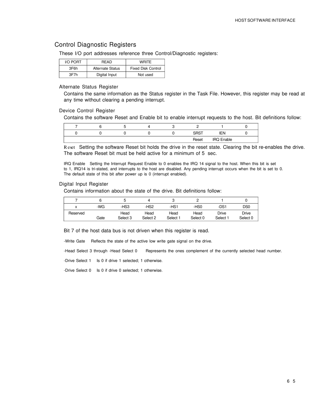
These I/O port addresses reference three Control/Diagnostic registers:
I/O PORT | READ | WRITE |
|
|
|
3F6h | Alternate Status | Fixed Disk Control |
|
|
|
3F7h | Digital Input | Not used |
|
|
|
Alternate Status Register
Contains the same information as the Status register in the Task File. However, this register may be read at any time without clearing a pending interrupt.
Device Control Register
Contains the software Reset and Enable bit to enable interrupt requests to the host. Bit definitions follow:
7 | 6 | 5 | 4 | 3 | 2 | 1 | 0 |
|
|
|
|
|
|
|
|
0 | 0 | 0 | 0 | 0 | SRST | IEN | 0 |
|
|
|
|
|
|
|
|
|
|
|
|
| Reset | IRQ Enable |
|
|
|
|
|
|
|
|
|
Reset – Setting the software Reset bit holds the drive in the reset state. Clearing the bit
IRQ Enable – Setting the Interrupt Request Enable to 0 enables the IRQ 14 signal to the host. When this bit is set
to 1, IRQ14 is
Digital Input Register
Contains information about the state of the drive. Bit definitions follow:
7 | 6 | 5 | 4 | 3 | 2 | 1 | 0 |
|
|
|
|
|
|
|
|
x | DS0 | ||||||
|
|
|
|
|
|
|
|
Reserved |
| Head | Head | Head | Head | Drive | Drive |
| Gate | Select 3 | Select 2 | Select 1 | Select 0 | Select 1 | Select 0 |
|
|
|
|
|
|
|
|
Bit 7 of the host data bus is not driven when this register is read.
6 – 5