APPENDIX #4 – PIN CONFIGURATIONS
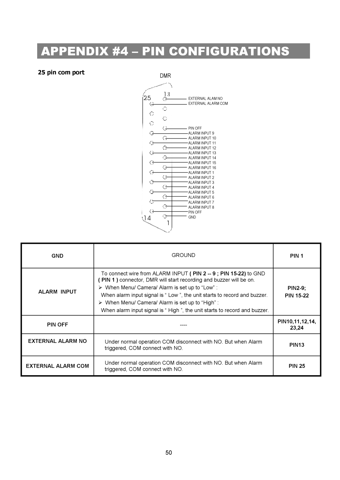
25 pin com port | DMR |
|
EXTERNAL ALAM NO
EXTERNAL ALARM COM
PIN OFF
ALARM INPUT 9
ALARM INPUT 10
ALARM INPUT 11
ALARM INPUT 12
ALARM INPUT 13
ALARM INPUT 14
ALARM INPUT 15
ALARM INPUT 16
ALARM INPUT 1
ALARM INPUT 2
ALARM INPUT 3
ALARM INPUT 4
ALARM INPUT 5
ALARM INPUT 6
ALARM INPUT 7
ALARM INPUT 8
PIN OFF
GND
GND | GROUND | PIN 1 | |
|
|
| |
| To connect wire from ALARM INPUT ( PIN 2 |
| |
| ( PIN 1 ) connector, DMR will start recording and buzzer will be on. |
| |
ALARM INPUT | Ø When Menu/ Camera/ Alarm is set up to “Low” : | ||
When alarm input signal is “ Low ”, the unit starts to record and buzzer. | PIN | ||
| |||
| Ø When Menu/ Camera/ Alarm is set up to “High” : |
| |
| When alarm input signal is “ High ”, the unit starts to record and buzzer. |
| |
|
|
| |
PIN OFF | PIN10,11,12,14, | ||
23,24 | |||
|
| ||
|
|
| |
EXTERNAL ALARM NO | Under normal operation COM disconnect with NO. But when Alarm | PIN13 | |
| triggered, COM connect with NO. | ||
|
| ||
|
|
| |
EXTERNAL ALARM COM | Under normal operation COM disconnect with NO. But when Alarm | PIN 25 | |
triggered, COM connect with NO. | |||
|
| ||
|
|
|
50