MDE/MDG6800, MDG5500
Membrane Pad Continuity Checks
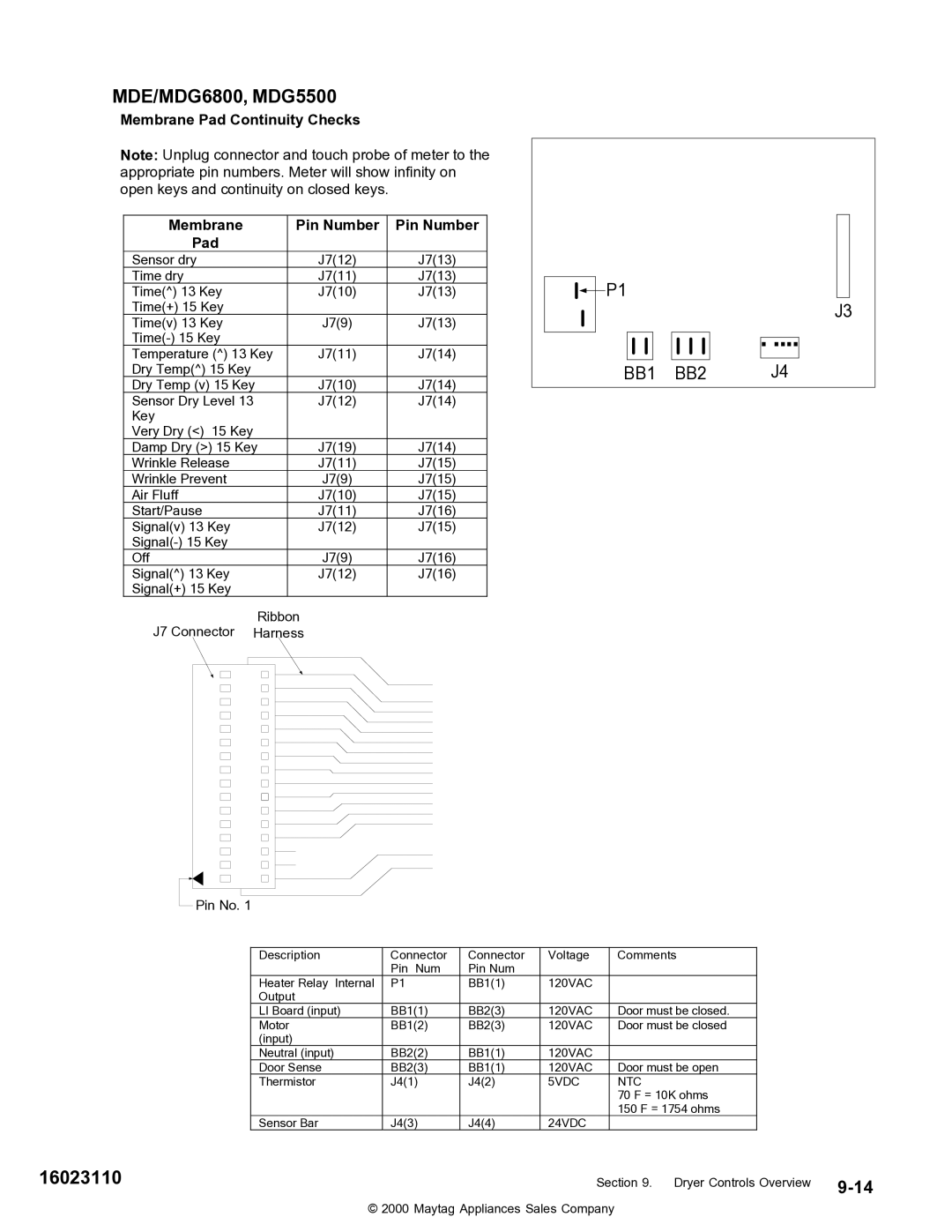
Note: Unplug connector and touch probe of meter to the appropriate pin numbers. Meter will show infinity on open keys and continuity on closed keys.
Membrane | Pin Number | Pin Number |
Pad |
|
|
Sensor dry | J7(12) | J7(13) |
Time dry | J7(11) | J7(13) |
Time(^) 13 Key | J7(10) | J7(13) |
Time(+) 15 Key |
|
|
Time(v) 13 Key | J7(9) | J7(13) |
|
| |
Temperature (^) 13 Key | J7(11) | J7(14) |
Dry Temp(^) 15 Key |
|
|
Dry Temp (v) 15 Key | J7(10) | J7(14) |
Sensor Dry Level 13 | J7(12) | J7(14) |
Key |
|
|
Very Dry (<) 15 Key |
|
|
Damp Dry (>) 15 Key | J7(19) | J7(14) |
Wrinkle Release | J7(11) | J7(15) |
Wrinkle Prevent | J7(9) | J7(15) |
Air Fluff | J7(10) | J7(15) |
Start/Pause | J7(11) | J7(16) |
Signal(v) 13 Key | J7(12) | J7(15) |
|
| |
Off | J7(9) | J7(16) |
Signal(^) 13 Key | J7(12) | J7(16) |
Signal(+) 15 Key |
|
|
Ribbon
J7 Connector Harness
![]() Pin No. 1
Pin No. 1
![]()
![]() P1
P1
J3
BB1 BB2 | J4 |
Description | Connector | Connector | Voltage | Comments |
| Pin Num | Pin Num |
|
|
Heater Relay Internal | P1 | BB1(1) | 120VAC |
|
Output |
|
|
|
|
LI Board (input) | BB1(1) | BB2(3) | 120VAC | Door must be closed. |
Motor | BB1(2) | BB2(3) | 120VAC | Door must be closed |
(input) |
|
|
|
|
Neutral (input) | BB2(2) | BB1(1) | 120VAC |
|
Door Sense | BB2(3) | BB1(1) | 120VAC | Door must be open |
Thermistor | J4(1) | J4(2) | 5VDC | NTC |
|
|
|
| 70 F = 10K ohms |
|
|
|
| 150 F = 1754 ohms |
Sensor Bar | J4(3) | J4(4) | 24VDC |
|
1602311016023110 | Section 9. Dryer Controls Overview |
© 2000 Maytag Appliances Sales Company