XCS350, XLS340, XLS360, XLS320 specifications
McIntosh has long been synonymous with high-quality audio equipment, and its XLS line of loudspeakers upholds this reputation. The XLS320, XLS340, XLS360, and XCS350 are all testament to McIntosh's commitment to delivering exceptional sound performance combined with innovative technology.Starting with the XLS320, this model serves as a compact, versatile speaker that is ideal for smaller spaces while delivering impressive audio quality. It features a 2-way design with a 1-inch titanium dome tweeter and dual 5.25-inch woofers that work in harmony to produce a broad frequency response. The XLS320 excels in creating clear, lifelike sound, making it suitable for both music and home theater applications. Its sleek design is complemented by a choice of finishes, allowing it to fit seamlessly into any decor.
Next is the XLS340, which expands on the strengths of the XLS320 by adding more power and room-filling sound. It incorporates a 3-way design, featuring a 1-inch titanium dome tweeter, a 5.25-inch midrange driver, and dual 8-inch woofers. This combination allows the XLS340 to handle a wider frequency range, producing deep bass and crisp highs that can immerse listeners in their audio experience. The speaker also utilizes advanced engineering techniques, such as a tapered cabinet design, which minimizes distortion and enhances clarity.
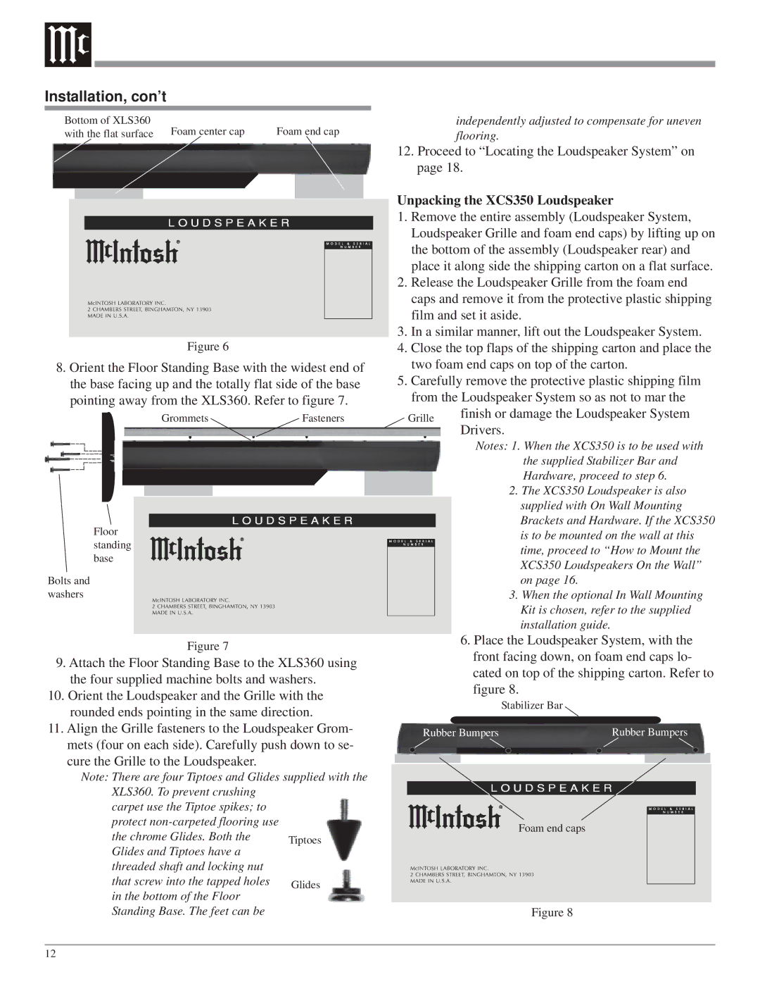
In the range, the XLS360 stands out as a floor-standing tower speaker, ideal for audiophiles who demand the best from their audio setup. This impressive loudspeaker features a sophisticated 4-driver configuration, including a 1-inch titanium dome tweeter, dual 5.25-inch midrange drivers, and dual 8-inch woofers. The XLS360 is engineered to deliver a powerful and dynamic soundstage, making it perfect for those who enjoy immersive home theater experiences or high-fidelity music playback. The speaker’s robust construction minimizes unwanted vibrations, ensuring that sound remains pure and undistorted.
Lastly, the XCS350 serves as the center channel speaker in the lineup, crucial for delivering clear dialogue in movies and shows. With its dual 5.25-inch woofers and 1-inch titanium dome tweeter, the XCS350 ensures that speech is both intelligible and engaging, making it an essential component of any home theater setup. Its design is optimized for seamless integration with other XLS models, delivering a balanced and cohesive audio experience across the entire sound system.
In summary, the McIntosh XLS series embodies cutting-edge audio technology and premium craftsmanship, making the XLS320, XLS340, XLS360, and XCS350 a coveted choice for audio enthusiasts. Each model brings unique features and characteristics that collectively enhance the audiophile experience, ensuring that McIntosh continues to lead in the realm of high-fidelity sound.

