Fig. 48: Attach the drive base to the tripod.
Fig. 49: Bolt the fork to the drive base.
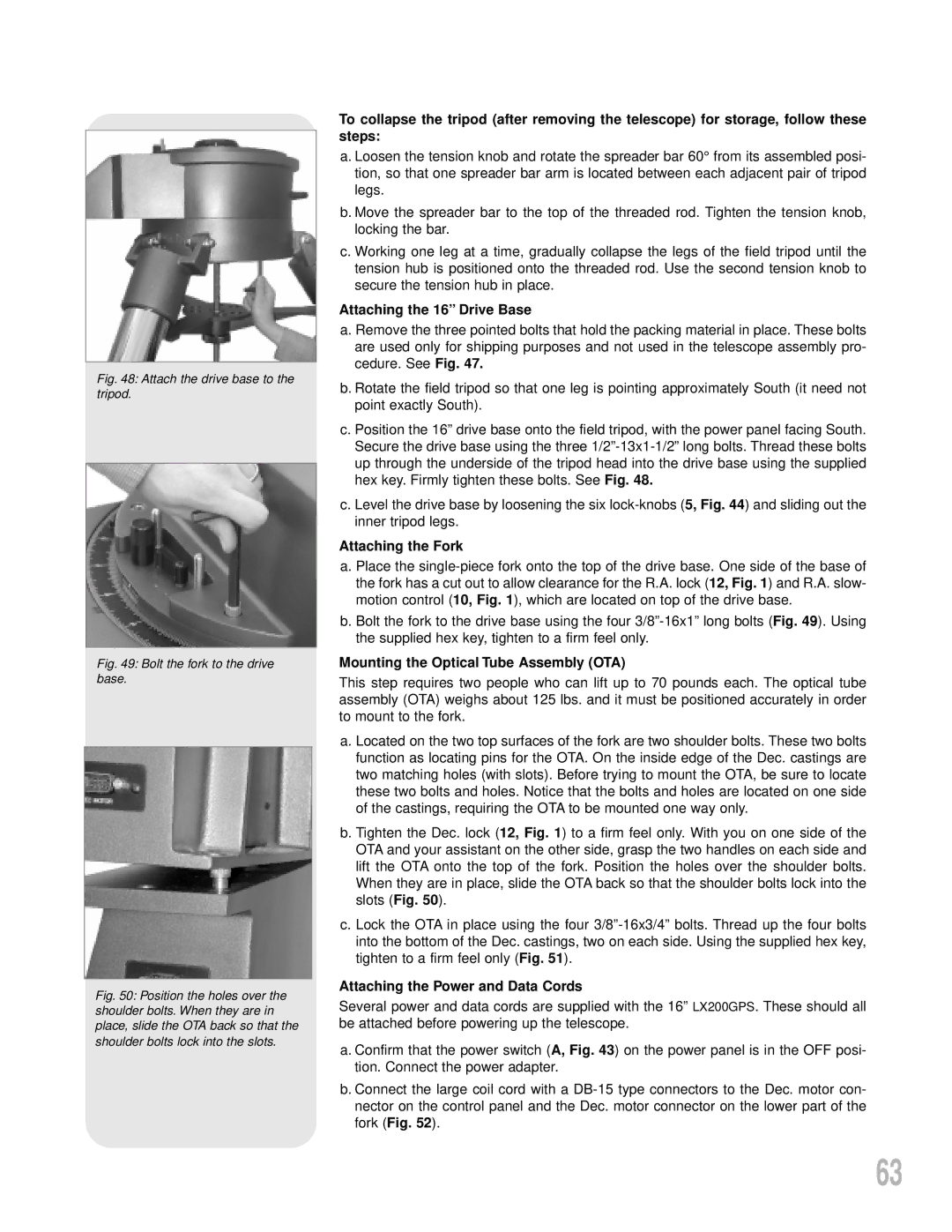
Fig. 50: Position the holes over the shoulder bolts. When they are in place, slide the OTA back so that the shoulder bolts lock into the slots.
To collapse the tripod (after removing the telescope) for storage, follow these steps:
a. Loosen the tension knob and rotate the spreader bar 60° from its assembled posi- tion, so that one spreader bar arm is located between each adjacent pair of tripod legs.
b. Move the spreader bar to the top of the threaded rod. Tighten the tension knob, locking the bar.
c. Working one leg at a time, gradually collapse the legs of the field tripod until the tension hub is positioned onto the threaded rod. Use the second tension knob to secure the tension hub in place.
Attaching the 16” Drive Base
a. Remove the three pointed bolts that hold the packing material in place. These bolts are used only for shipping purposes and not used in the telescope assembly pro- cedure. See Fig. 47.
b. Rotate the field tripod so that one leg is pointing approximately South (it need not point exactly South).
c. Position the 16” drive base onto the field tripod, with the power panel facing South. Secure the drive base using the three
c. Level the drive base by loosening the six
Attaching the Fork
a. Place the
b. Bolt the fork to the drive base using the four
Mounting the Optical Tube Assembly (OTA)
This step requires two people who can lift up to 70 pounds each. The optical tube assembly (OTA) weighs about 125 lbs. and it must be positioned accurately in order to mount to the fork.
a. Located on the two top surfaces of the fork are two shoulder bolts. These two bolts function as locating pins for the OTA. On the inside edge of the Dec. castings are two matching holes (with slots). Before trying to mount the OTA, be sure to locate these two bolts and holes. Notice that the bolts and holes are located on one side of the castings, requiring the OTA to be mounted one way only.
b. Tighten the Dec. lock (12, Fig. 1) to a firm feel only. With you on one side of the OTA and your assistant on the other side, grasp the two handles on each side and lift the OTA onto the top of the fork. Position the holes over the shoulder bolts. When they are in place, slide the OTA back so that the shoulder bolts lock into the slots (Fig. 50).
c. Lock the OTA in place using the four
Attaching the Power and Data Cords
Several power and data cords are supplied with the 16” LX200GPS. These should all be attached before powering up the telescope.
a. Confirm that the power switch (A, Fig. 43) on the power panel is in the OFF posi- tion. Connect the power adapter.
b. Connect the large coil cord with a
63