QUICK-START GUIDE
It is recommended that you attach the supplied tripod to the LX200GPS for observing. Perform the telescope and Autostar II setup indoors in the light so that you become familiar with the parts and operation before moving the tele- scope outside into the dark for observing. The setup is the same for the standard field tripod and the giant field tripod.
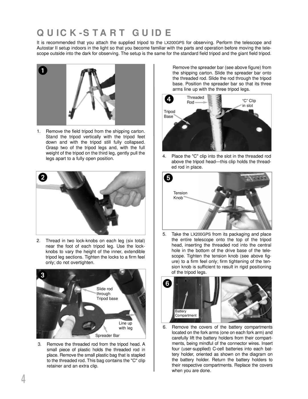
Remove the spreader bar (see above figure) from the shipping carton. Slide the spreader bar onto the threaded rod. Slide the rod through the tripod base. Position the spreader bar so that its three arms line up with the three tripod legs.
Threaded
Rod![]() “C” Clip
“C” Clip
Tripod Base
![]() in slot
in slot
1.Remove the field tripod from the shipping carton. Stand the tripod vertically with the tripod feet down and with the tripod still fully collapsed. Grasp two of the tripod legs and, with the full weight of the tripod on the third leg, gently pull the legs apart to a fully open position.
4.Place the "C" clip into the slot in the threaded rod above the tripod
Tension
Knob
2.Thread in two
Slide rod through Tripod base
Line up with leg
Spreader Bar
3.Remove the threaded rod from the tripod head. A small piece of plastic holds the threaded rod in place. Remove the small plastic bag that is stapled to the threaded rod. This bag contains the "C" clip retainer and an extra clip.
5.Take the LX200GPS from its packaging and place the entire telescope onto the top of the tripod head, inserting the threaded rod into the central hole in the bottom of the drive base of the tele- scope. Tighten the tension knob (see above fig- ure) to a firm feel only; firm tightening of the ten- sion knob is sufficient to result in rigid positioning of the tripod legs.
Battery
Compartment
6.Remove the covers of the battery compartments located on the fork arms (one on each fork arm) and carefully lift the battery holders from their compart- ments, being mindful of the connector wires. Insert four
4