| Functional Details |
Using multiple inputs to control one DAC output
Update mode: Rising edge, for each of two channels
Criteria used: Inside window, for each of two channels
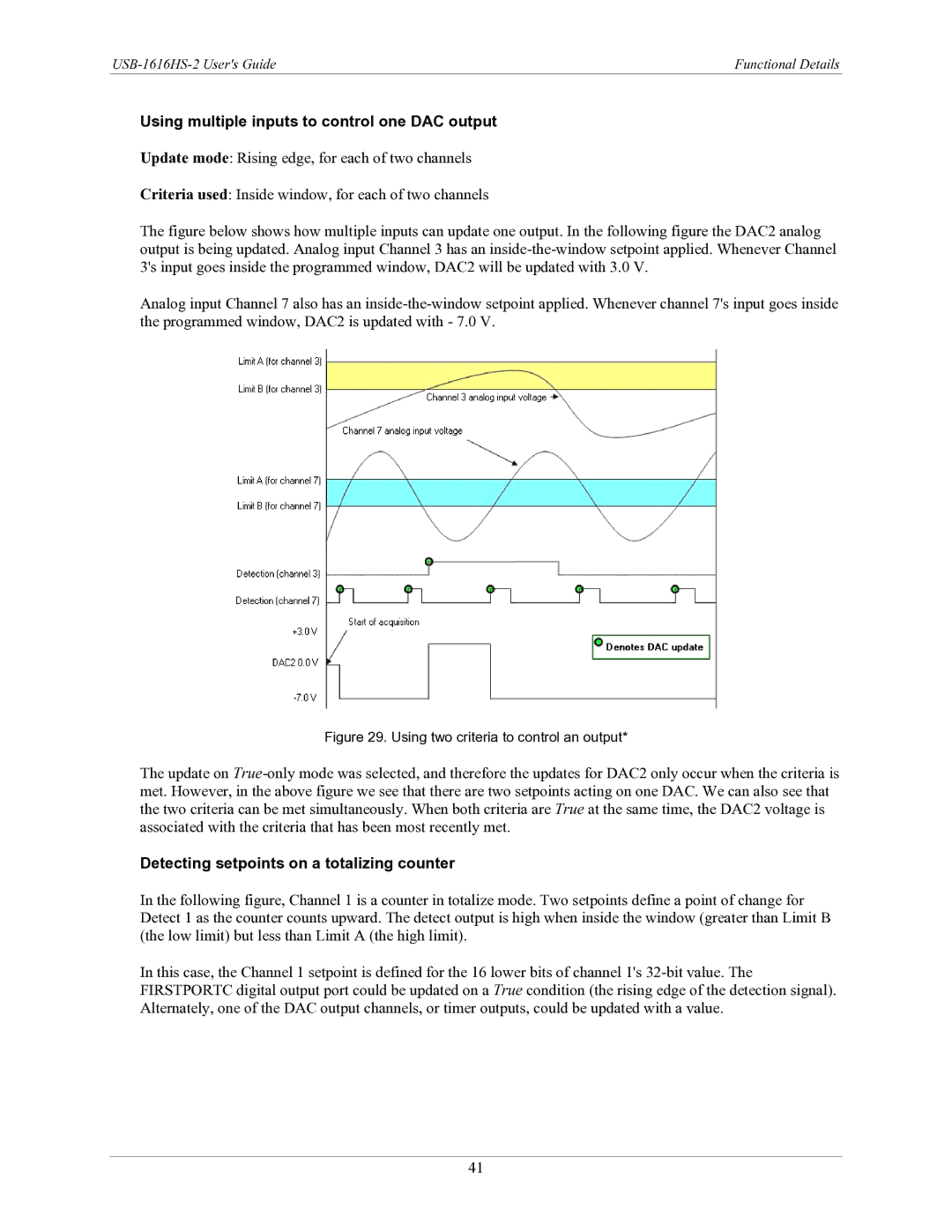
The figure below shows how multiple inputs can update one output. In the following figure the DAC2 analog output is being updated. Analog input Channel 3 has an inside-the-window setpoint applied. Whenever Channel 3's input goes inside the programmed window, DAC2 will be updated with 3.0 V.
Analog input Channel 7 also has an
Figure 29. Using two criteria to control an output*
The update on
Detecting setpoints on a totalizing counter
In the following figure, Channel 1 is a counter in totalize mode. Two setpoints define a point of change for Detect 1 as the counter counts upward. The detect output is high when inside the window (greater than Limit B (the low limit) but less than Limit A (the high limit).
In this case, the Channel 1 setpoint is defined for the 16 lower bits of channel 1's
41