B. WALL MOUNTING (No Standard Wall Jack)
1.Drill two holes with a vertical distance between the two marked
| positions of 3 15/16" (100 mm) as shown in Figure 6. | 3 15/16” |
2. | Drive a screw into each of the holes. Tighten them to the end | (100 mm) |
| of the screw line, only leaving the smooth part of the screw head |
|
| outside the wall. |
|
|
| |
3. | Hang the unit onto the screws, then slide it down firmly to | (Figure 6) |
| fasten the base securely. | |
|
|
BELT CLIP INSTRUCTION
Clamp the belt clip at the back of the handset as shown in Figure 7.
Belt Clip
(Figure 7)
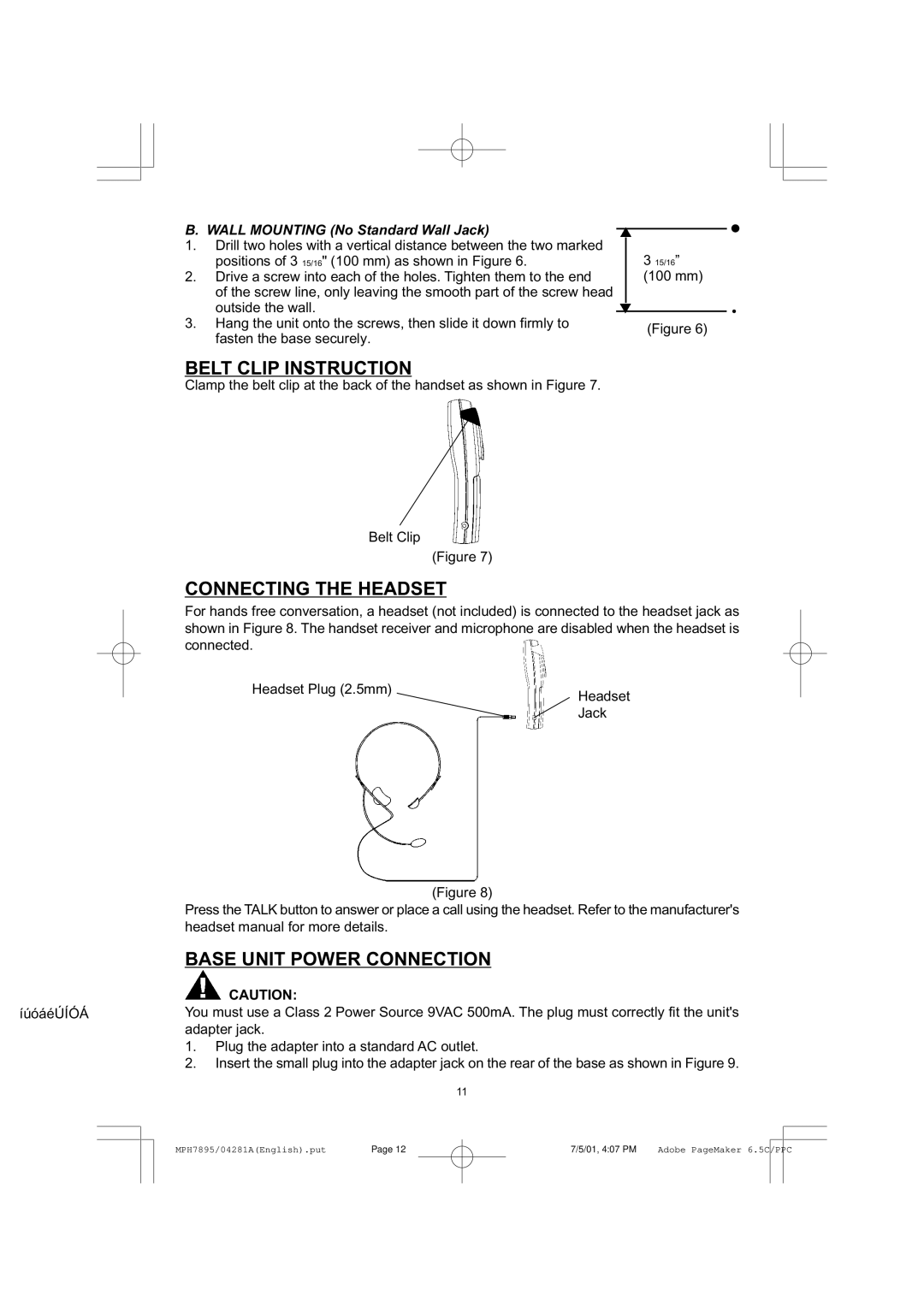
CONNECTING THE HEADSET
For hands free conversation, a headset (not included) is connected to the headset jack as shown in Figure 8. The handset receiver and microphone are disabled when the headset is connected.
Headset Plug (2.5mm) | Headset |
| |
| Jack |
(Figure 8)
Press the TALK button to answer or place a call using the headset. Refer to the manufacturer's headset manual for more details.
BASE UNIT POWER CONNECTION
CAUTION:
íúóáéÚÍÓÁYou must use a Class 2 Power Source 9VAC 500mA. The plug must correctly fit the unit's adapter jack.
1.Plug the adapter into a standard AC outlet.
2.Insert the small plug into the adapter jack on the rear of the base as shown in Figure 9.
11
| Page 12 | 7/5/01, 4:07 PM |
|
|
|
MPH7895/04281A(English).put | Adobe PageMaker 6.5C/PPC |
| |||
|
|
|
|
|
|