PLC CPUs | 3 |
64 MHz,
August 1997
DMake sure that rack power is off.
DInstall the CSE 925 module in slot 1 of rack 0 (see Figure 2).
DTurn on power.
The module should power up and the top LED should blink. When the diagnostics have completed successfully, the top LED stays on and the second and third LEDs are off. The fourth LED is off if the keyswitch is in the OFF position. The CPU is now ready to be programmed.
After the program has been verified the toggle switch may be moved to the appropriate operation mode position. The LEDs indicate the position of the toggle switch, memory protection status, and the state of the program.
The IC641
|
|
|
| SERIAL | a45301 |
|
|
| RACK 0 |
| PROGRAMMER |
P | C | B | P | G |
|
S | P | T | C | B |
|
| U | M | M | C |
|
|
|
|
| or |
|
|
|
|
| N |
|
|
|
|
| B |
|
|
|
|
| C |
|
|
|
|
|
| * |
ONE |
|
| IC66* I/O BUS (7500 FEET (2285 METERS) | ||
METER |
| RACK 1 |
|
| |
|
|
|
|
|
|
B
R
M
IC66*
I/O BLOCK
NOTE
RACK 7
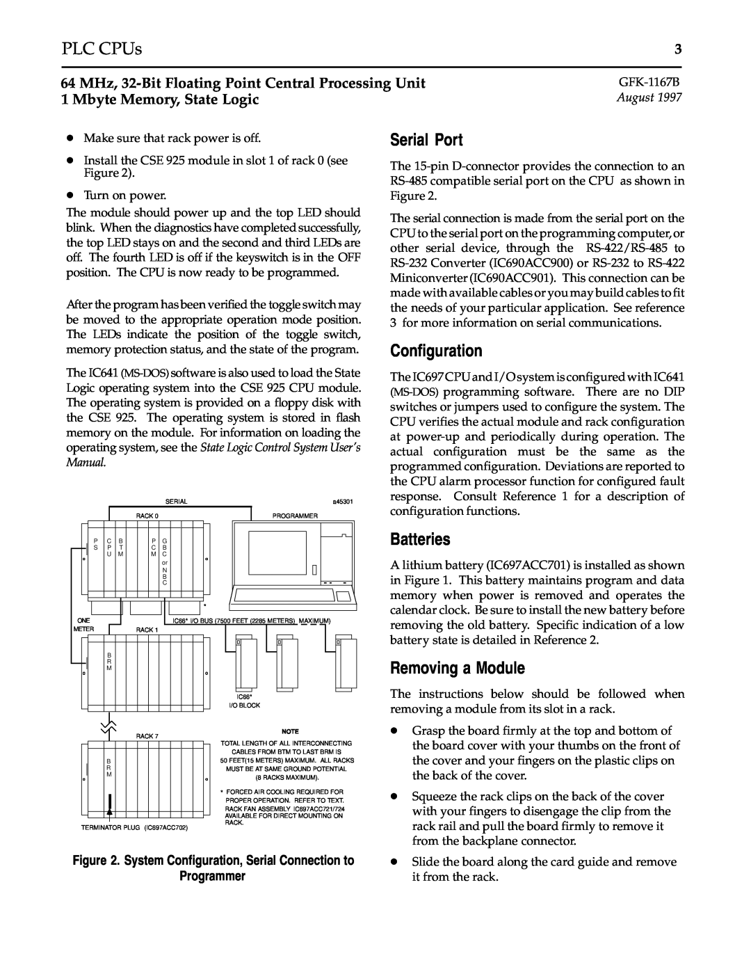
Serial Port
The
The serial connection is made from the serial port on the CPU to the serial port on the programming computer,or other serial device, through the
Configuration
The IC697 CPU and I/O system is configured with IC641
Batteries
A lithium battery (IC697ACC701) is installed as shown in Figure 1. This battery maintains program and data memory when power is removed and operates the calendar clock. Be sure to install the new battery before removing the old battery. Specific indication of a low battery state is detailed in Reference 2.
Removing a Module
The instructions below should be followed when removing a module from its slot in a rack.
D Grasp the board firmly at the top and bottom of |
B |
R |
M |
TERMINATOR PLUG (IC697ACC702)
TOTAL LENGTH OF ALL INTERCONNECTING
CABLES FROM BTM TO LAST BRM IS
50 FEET(15 METERS) MAXIMUM. ALL RACKS MUST BE AT SAME GROUND POTENTIAL
(8 RACKS MAXIMUM).
*FORCED AIR COOLING REQUIRED FOR PROPER OPERATION. REFER TO TEXT.
RACK FAN ASSEMBLY IC697ACC721/724
AVAILABLE FOR DIRECT MOUNTING ON RACK.
the board cover with your thumbs on the front of |
the cover and your fingers on the plastic clips on |
the back of the cover. |
D Squeeze the rack clips on the back of the cover |
with your fingers to disengage the clip from the |
rack rail and pull the board firmly to remove it |
from the backplane connector. |
Figure 2. System Configuration, Serial Connection to
Programmer
D Slide the board along the card guide and remove |
it from the rack. |