WEM INSTALLATION & OPERATION (cont’d)
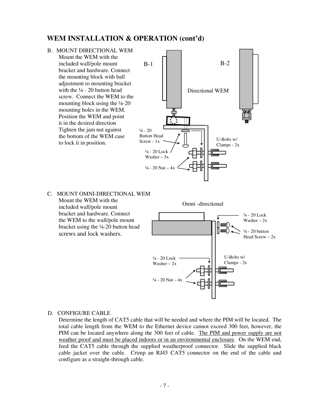
B.MOUNT DIRECTIONAL WEM Mount the WEM with the included wall/pole mount bracket and hardware. Connect the mounting block with ball adjustment to mounting bracket with the ¼ - 20 button head screw. Connect the WEM to the mounting block using the
it in the desired direction Tighten the jam nut against the bottom of the WEM case to lock it in position.
Directional WEM
¼ - 20 Button Head
Screw - 1xU-Bolts w/
Clamps - 2x
¼ - 20 Lock
Washer – 5x
¼ - 20 Nut – 4x ![]()
C. MOUNT |
Mount the WEM with the |
included wall/pole mount |
Omni
bracket and hardware. Connect |
the WEM to the wall/pole mount |
bracket using the |
screws and lock washers. |
¼- 20 Lock Washer – 2x
¼ - 20 Lock
Washer – 2x
¼ - 20 button Head Screw – 2x
Clamps - 2x
¼ - 20 Nut – 4x
D. CONFIGURE CABLE
Determine the length of CAT5 cable that will be needed and where the PIM will be located. The total cable length from the WEM to the Ethernet device cannot exceed 300 feet, however, the PIM can be located anywhere along the 300 feet of cable. The PIM and power supply are not weather proof and must be placed indoors or in an environmental enclosure. On the WEM end, feed the CAT5 cable through the supplied weatherproof connector. Slide the supplied black cable jacket over the cable. Crimp an RJ45 CAT5 connector on the end of the cable and configure as a
- 7 -