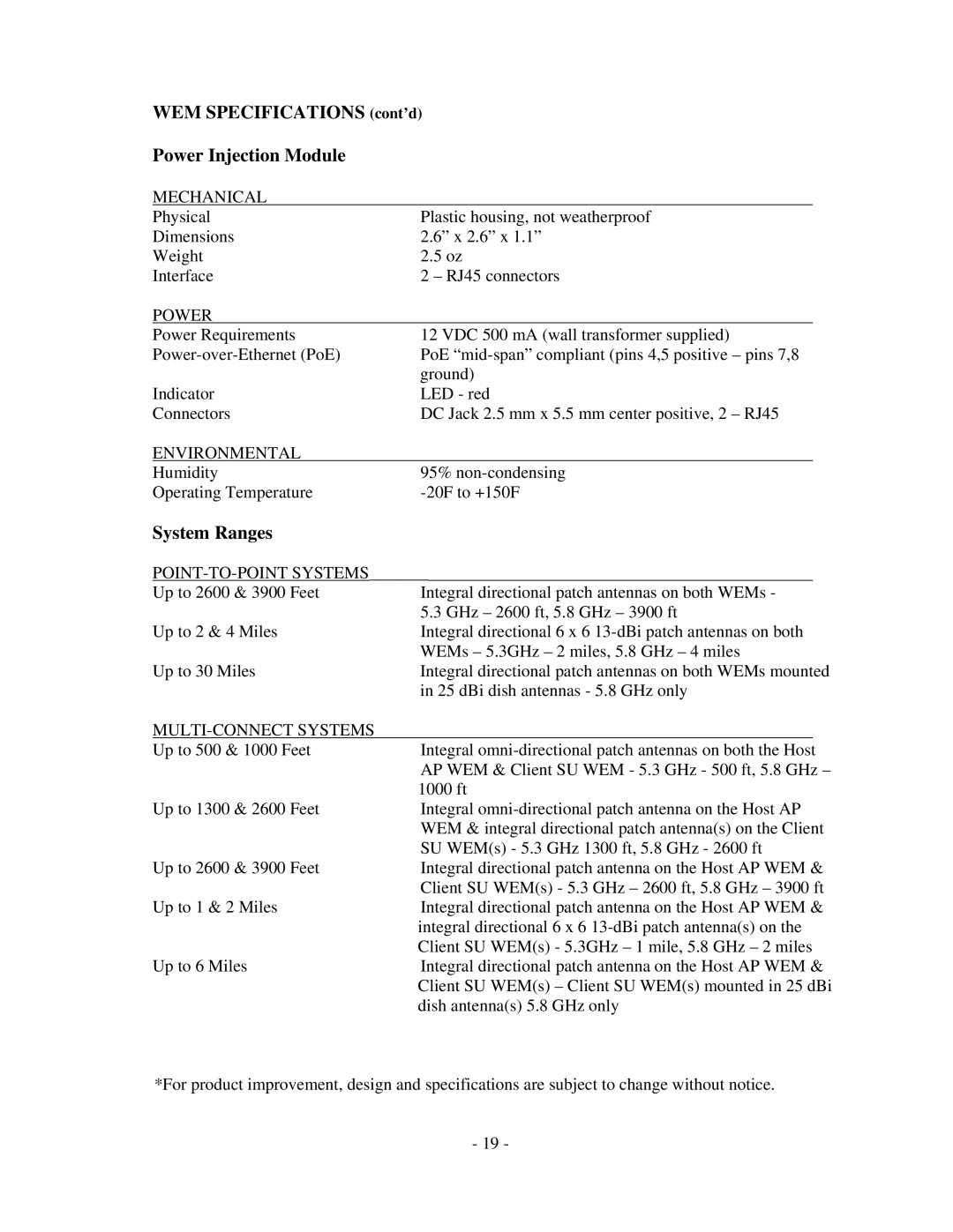
WEM SPECIFICATIONS (cont’d)
Power Injection Module
MECHANICAL
Physical | Plastic housing, not weatherproof |
Dimensions | 2.6” x 2.6” x 1.1” |
Weight | 2.5 oz |
Interface | 2 – RJ45 connectors |
POWER |
|
Power Requirements | 12 VDC 500 mA (wall transformer supplied) |
PoE | |
| ground) |
Indicator | LED - red |
Connectors | DC Jack 2.5 mm x 5.5 mm center positive, 2 – RJ45 |
ENVIRONMENTAL |
|
Humidity | 95% |
Operating Temperature |
System Ranges
POINT-TO-POINT SYSTEMS_______
Up to 2600 & 3900 Feet | Integral directional patch antennas on both WEMs - | |
| 5.3 GHz – 2600 ft, 5.8 GHz – 3900 ft | |
Up to 2 & 4 Miles | Integral directional 6 x 6 | |
| WEMs – 5.3GHz – 2 miles, 5.8 GHz – 4 miles | |
Up to 30 Miles | Integral directional patch antennas on both WEMs mounted | |
| in 25 dBi dish antennas - 5.8 GHz only | |
|
|
|
Up to 500 & 1000 Feet | Integral |
|
| AP WEM & Client SU WEM - 5.3 GHz - 500 ft, 5.8 GHz – | |
| 1000 ft | |
Up to 1300 & 2600 Feet | Integral | |
| WEM & integral directional patch antenna(s) on the Client | |
| SU WEM(s) - 5.3 GHz 1300 ft, 5.8 GHz - 2600 ft | |
Up to 2600 & 3900 Feet | Integral directional patch antenna on the Host AP WEM & | |
| Client SU WEM(s) - 5.3 GHz – 2600 ft, 5.8 GHz – 3900 ft | |
Up to 1 & 2 Miles | Integral directional patch antenna on the Host AP WEM & | |
| integral directional 6 x 6 | |
| Client SU WEM(s) - 5.3GHz – 1 mile, 5.8 GHz – 2 miles | |
Up to 6 Miles | Integral directional patch antenna on the Host AP WEM & | |
| Client SU WEM(s) – Client SU WEM(s) mounted in 25 dBi | |
| dish antenna(s) 5.8 GHz only | |
*For product improvement, design and specifications are subject to change without notice.
- 19 -
