WES CONNECTION DIAGRAM
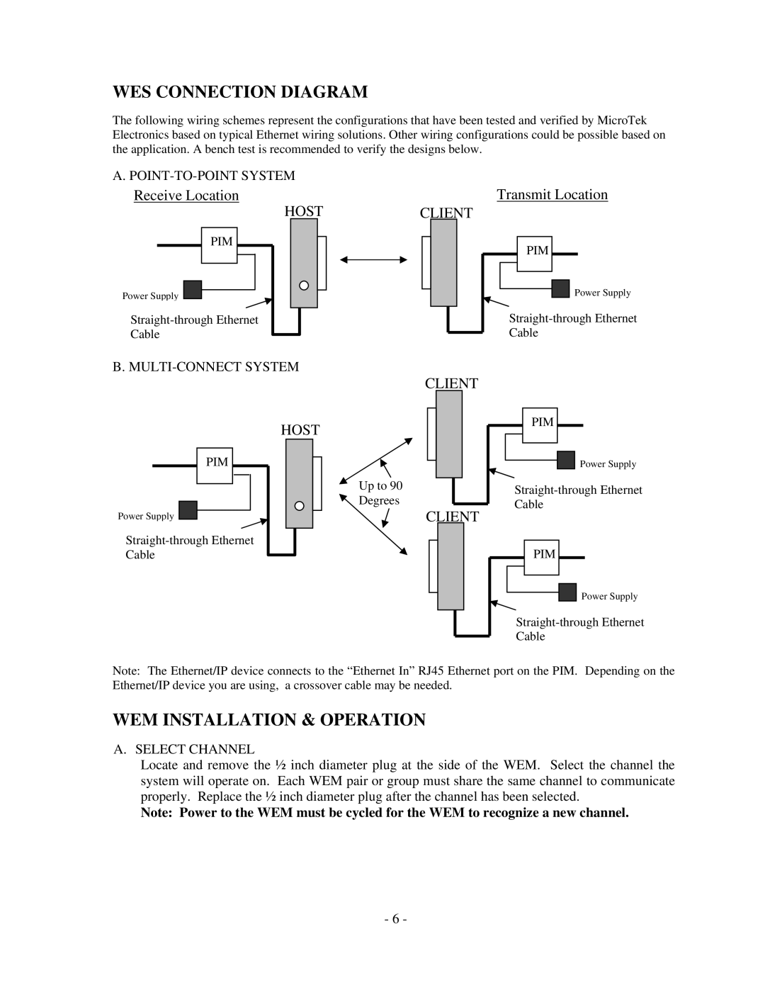
The following wiring schemes represent the configurations that have been tested and verified by MicroTek Electronics based on typical Ethernet wiring solutions. Other wiring configurations could be possible based on the application. A bench test is recommended to verify the designs below.
A. |
|
Receive Location | Transmit Location |
HOSTCLIENT
PIM |
Power Supply |
Cable |
PIM |
Power Supply |
Cable |
B. |
CLIENT
HOST |
PIM |
Power Supply |
Cable |
Up to 90
Degrees
CLIENT
PIM |
Power Supply |
Cable |
PIM |
Power Supply |
Cable |
Note: The Ethernet/IP device connects to the “Ethernet In” RJ45 Ethernet port on the PIM. Depending on the Ethernet/IP device you are using, a crossover cable may be needed.
WEM INSTALLATION & OPERATION
A. SELECT CHANNEL
Locate and remove the ½ inch diameter plug at the side of the WEM. Select the channel the system will operate on. Each WEM pair or group must share the same channel to communicate properly. Replace the ½ inch diameter plug after the channel has been selected.
Note: Power to the WEM must be cycled for the WEM to recognize a new channel.
- 6 -