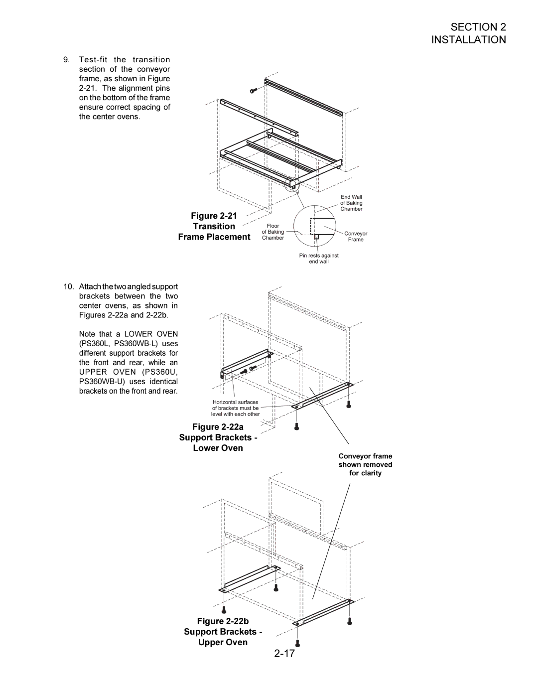
Middleby Marshall 2-17, Transition Frame Placement, 22a Support Brackets Lower Oven -22b

Models: Oven

1 30
Download 30 pages 19.19 Kb
Page 17
Image 17
Transition

9.Test-fit the transition section of the conveyor

frame, as shown in Figure 2-21. The alignment pins on the bottom of the frame ensure correct spacing of the center ovens.

Figure 2-21

Transition

Frame Placement

10.Attach the two angled support brackets between the two center ovens, as shown in Figures 2-22a and 2-22b.

Note that a LOWER OVEN (PS360L, PS360WB-L) uses different support brackets for the front and rear, while an UPPER OVEN (PS360U, PS360WB-U) uses identical brackets on the front and rear.

Figure 2-22a

Support Brackets -

Lower Oven

Figure 2-22b

Support Brackets -

Upper Oven

SECTION 2

INSTALLATION

Conveyor frame shown removed for clarity

2-17

Page 17
Image 17
Middleby Marshall 2-17, Transition Frame Placement, 22a Support Brackets Lower Oven -22b, Support Brackets Upper Oven