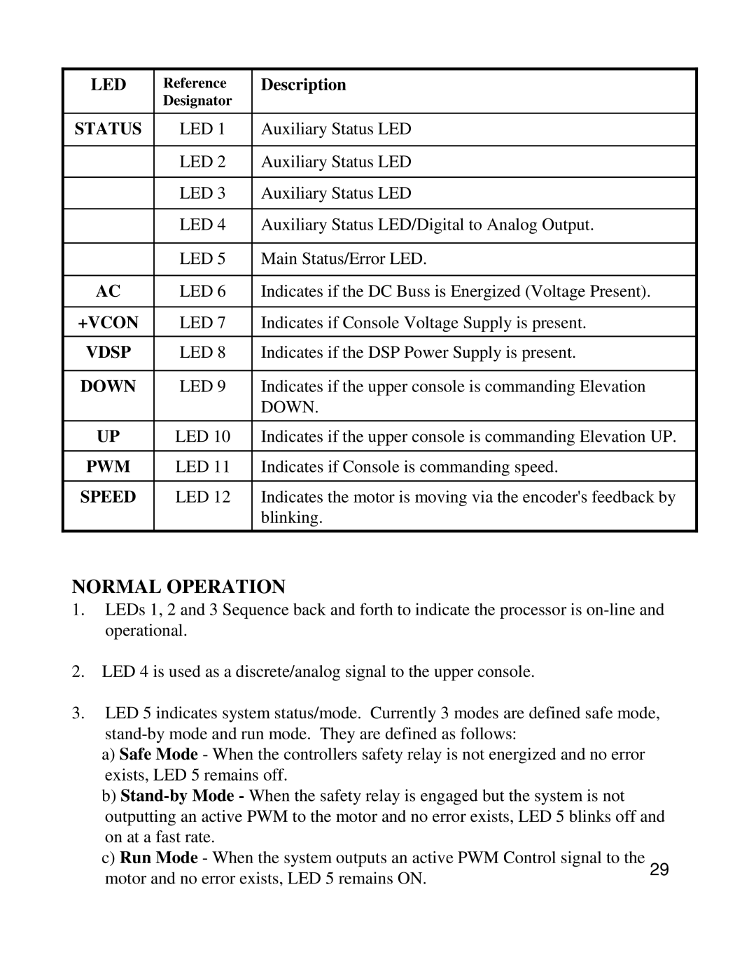
LED | Reference | Description |
| Designator |
|
|
|
|
STATUS | LED 1 | Auxiliary Status LED |
|
|
|
| LED 2 | Auxiliary Status LED |
|
|
|
| LED 3 | Auxiliary Status LED |
|
|
|
| LED 4 | Auxiliary Status LED/Digital to Analog Output. |
|
|
|
| LED 5 | Main Status/Error LED. |
|
|
|
AC | LED 6 | Indicates if the DC Buss is Energized (Voltage Present). |
|
|
|
+VCON | LED 7 | Indicates if Console Voltage Supply is present. |
|
|
|
VDSP | LED 8 | Indicates if the DSP Power Supply is present. |
|
|
|
DOWN | LED 9 | Indicates if the upper console is commanding Elevation |
|
| DOWN. |
|
|
|
UP | LED 10 | Indicates if the upper console is commanding Elevation UP. |
|
|
|
PWM | LED 11 | Indicates if Console is commanding speed. |
|
|
|
SPEED | LED 12 | Indicates the motor is moving via the encoder's feedback by |
|
| blinking. |
|
|
|
NORMAL OPERATION
1.LEDs 1, 2 and 3 Sequence back and forth to indicate the processor is
2.LED 4 is used as a discrete/analog signal to the upper console.
3.LED 5 indicates system status/mode. Currently 3 modes are defined safe mode,
a)Safe Mode - When the controllers safety relay is not energized and no error exists, LED 5 remains off.
b)
c)Run Mode - When the system outputs an active PWM Control signal to the
motor and no error exists, LED 5 remains ON.29