4-5. Installing Electrode Holder And Work Clamp
3
2
4 | 5 |
1
6
8
Tools Needed:
9
1/2 in7 1/4 in
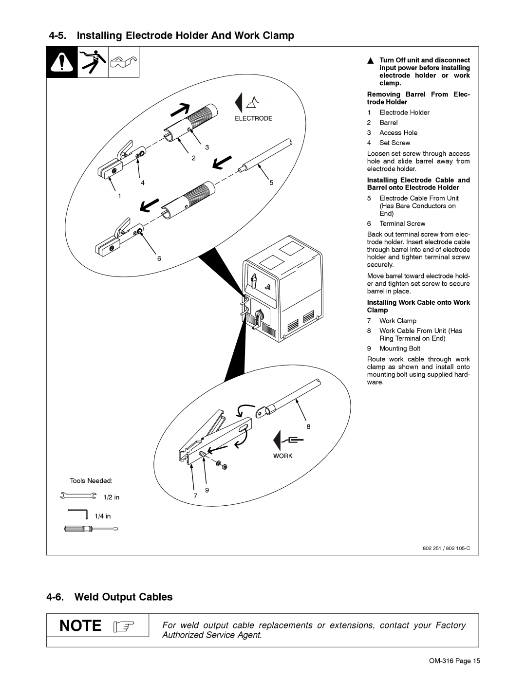
YTurn Off unit and disconnect input power before installing electrode holder or work clamp.
Removing Barrel From Elec- trode Holder
1Electrode Holder
2Barrel
3Access Hole
4Set Screw
Loosen set screw through access hole and slide barrel away from electrode holder.
Installing Electrode Cable and Barrel onto Electrode Holder
5Electrode Cable From Unit (Has Bare Conductors on End)
6Terminal Screw
Back out terminal screw from elec- trode holder. Insert electrode cable through barrel into end of electrode holder and tighten terminal screw securely.
Move barrel toward electrode hold- er and tighten set screw to secure barrel in place.
Installing Work Cable onto Work Clamp
7Work Clamp
8Work Cable From Unit (Has Ring Terminal on End)
9Mounting Bolt
Route work cable through work clamp as shown and install onto mounting bolt using supplied hard- ware.
802 251 / 802
4-6. Weld Output Cables
NOTE
For weld output cable replacements or extensions, contact your Factory Authorized Service Agent.