6-3. Reinstalling Amperage Adjustment Indicator
5
6
2
7
4
3 ![]()
1
3
For 225 A models, X = 2−1/2 in For 300 A models, X = 2−3/8 in
X
Viewed from right side of unit.
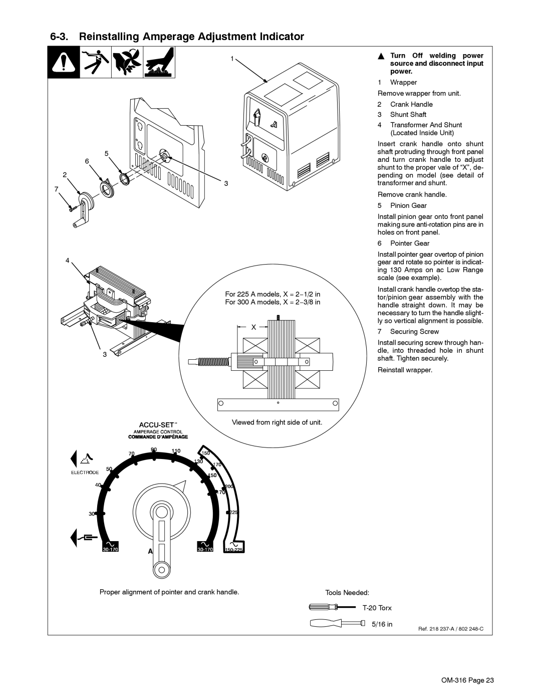
YTurn Off welding power source and disconnect input power.
1 Wrapper
Remove wrapper from unit.
2Crank Handle
3Shunt Shaft
4Transformer And Shunt (Located Inside Unit)
Insert crank handle onto shunt shaft protruding through front panel and turn crank handle to adjust shunt to the proper vale of “X”, de- pending on model (see detail of transformer and shunt.
Remove crank handle.
5 Pinion Gear
Install pinion gear onto front panel making sure
6 Pointer Gear
Install pointer gear overtop of pinion gear and rotate so pointer is indicat- ing 130 Amps on ac Low Range scale (see example).
Install crank handle overtop the sta- tor/pinion gear assembly with the handle straight down. It may be necessary to turn the handle slight- ly so vertical alignment is possible.
7 Securing Screw
Install securing screw through han- dle, into threaded hole in shunt shaft. Tighten securely.
Reinstall wrapper.
Proper alignment of pointer and crank handle. | Tools Needed: |
T-20 Torx
5/16 in
Ref. 218