4-10. Connecting Input Power
| 1 |
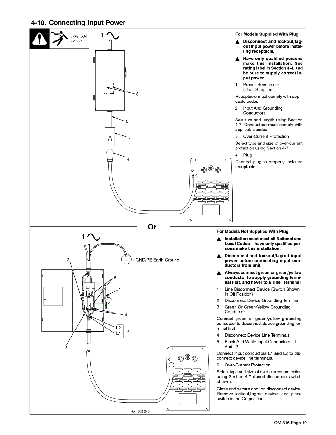
| For Models Supplied With Plug | |
|
|
| Y Disconnect and lockout/tag- | |
|
|
|
| out input power before instal- |
|
|
|
| ling receptacle. |
|
|
| Y Have only qualified persons | |
|
|
|
| make this installation. See |
|
|
|
| rating label in Section |
|
|
|
| be sure to supply correct in- |
|
|
|
| put power. |
|
|
| 1 | Proper Receptacle |
|
| 3 |
| |
|
| Receptacle must comply with appli- | ||
|
|
| ||
|
|
| cable codes. | |
|
|
| 2 | Input And Grounding |
|
|
|
| Conductors |
2 |
| See size and length using Section | ||
|
|
| ||
|
|
| applicable codes. | |
1 |
| 3 | ||
| Select type and size of | |||
|
|
| ||
|
|
| protection using Section | |
4 |
| 4 | Plug | |
| Connect plug to properly installed | |||
|
|
| ||
|
|
| receptacle. | |
|
|
| Or | For Models Not Supplied With Plug | |
1 |
|
|
| ||
|
|
| Y Installation must meet all National and | ||
|
|
|
|
| Local Codes − have only qualified per- |
|
|
|
|
| sons make this installation. |
2 |
|
| =GND/PE Earth Ground | Y Disconnect and lockout/tagout input | |
|
|
| power before connecting input con- | ||
|
|
|
|
| ductors from unit. |
|
|
|
| Y Always connect green or green/yellow | |
6 |
|
|
|
| conductor to supply grounding termi- |
|
|
|
|
| nal first, and never to a line terminal. |
1 |
|
|
| 1 | Line Disconnect Device (Switch Shown |
|
|
|
|
| In Off Position) |
|
|
|
| 2 | Disconnect Device Grounding Terminal |
|
|
|
| 3 | Green Or Green/Yellow Grounding |
| 4 |
|
|
| Conductor |
|
|
| Connect green or green/yellow grounding | ||
|
|
|
| ||
L2 |
|
|
| conductor to disconnect device grounding ter- | |
| 5 |
| minal first. | ||
L1 |
|
| 4 | Disconnect Device Line Terminals | |
|
|
|
| ||
|
|
|
| 5 | Black And White Input Conductors L1 |
3 |
|
|
|
| And L2 |
Connect input conductors L1 and L2 to dis- connect device line terminals.
6
Select type and size of
Close and secure door on disconnect device. Remove lockout/tagout device, and place switch in the On position.
Ref. 802 246