NOTE
Follow applicable electrical codes and have a competent electrician make internal connections. Note the input amperes as stated in Section
1
Power Switch
S1 Terminals
2
230V Connection
6 | 1 | |
To Fan | ||
|
To Fan
73
4
3
2
To Fan
2
11
115V Connection
6 | To Fan |
|
3
2 |
|
8 | 4 |
8
10
![]() 5
5
| 5 |
Tools Needed: |
|
5/16, 3/8 in | 9 |
(cut tie wraps) |
|
4
7/16 in
Ref. 802
YTurn Off unit and disconnect input power.
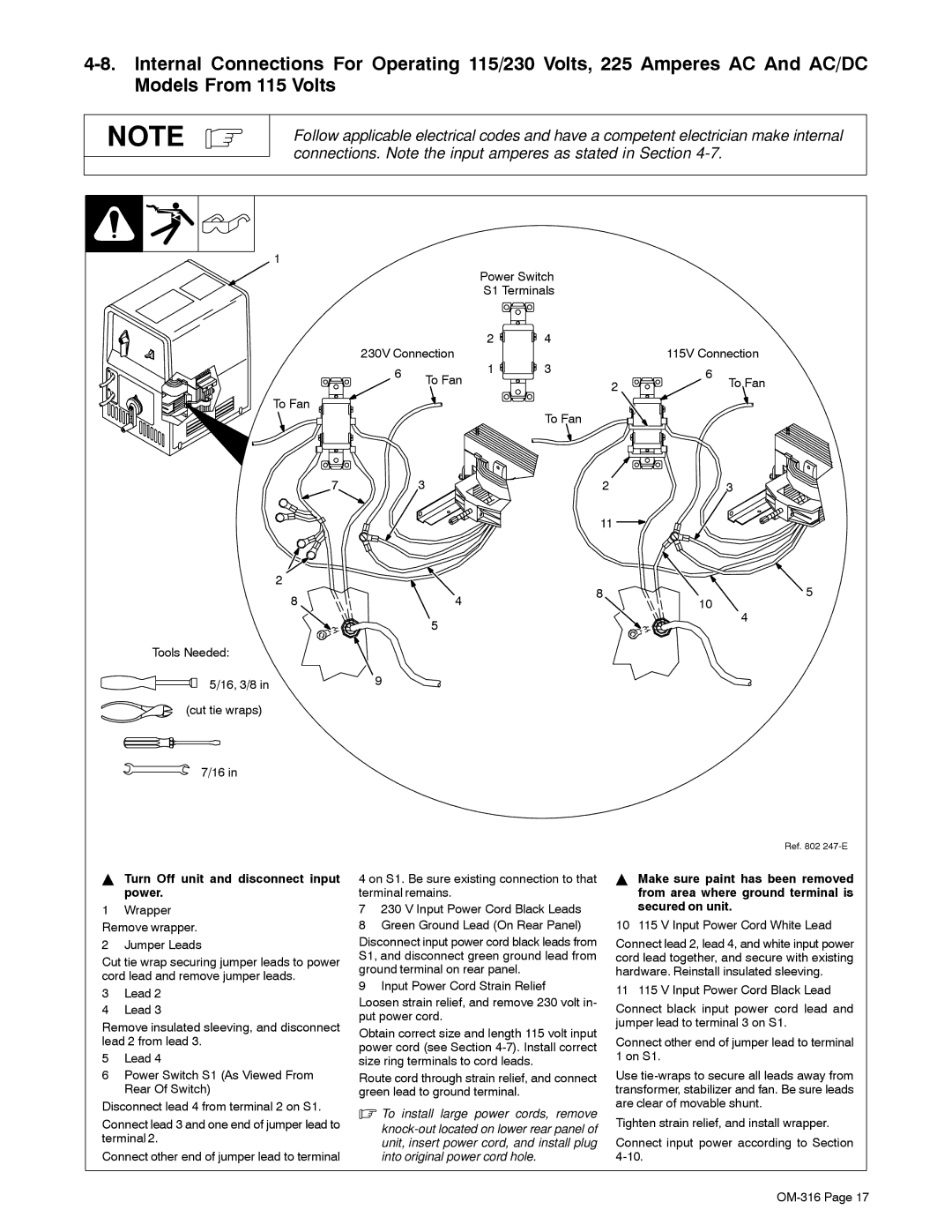
1Wrapper Remove wrapper.
2Jumper Leads
Cut tie wrap securing jumper leads to power cord lead and remove jumper leads.
3Lead 2
4Lead 3
Remove insulated sleeving, and disconnect lead 2 from lead 3.
5Lead 4
6Power Switch S1 (As Viewed From Rear Of Switch)
Disconnect lead 4 from terminal 2 on S1.
Connect lead 3 and one end of jumper lead to terminal 2.
Connect other end of jumper lead to terminal
4 on S1. Be sure existing connection to that terminal remains.
7230 V Input Power Cord Black Leads
8Green Ground Lead (On Rear Panel)
Disconnect input power cord black leads from S1, and disconnect green ground lead from ground terminal on rear panel.
9 Input Power Cord Strain Relief
Loosen strain relief, and remove 230 volt in- put power cord.
Obtain correct size and length 115 volt input power cord (see Section
Route cord through strain relief, and connect green lead to ground terminal.
.To install large power cords, remove
YMake sure paint has been removed from area where ground terminal is secured on unit.
10 115 V Input Power Cord White Lead
Connect lead 2, lead 4, and white input power cord lead together, and secure with existing hardware. Reinstall insulated sleeving.
11 115 V Input Power Cord Black Lead
Connect black input power cord lead and jumper lead to terminal 3 on S1.
Connect other end of jumper lead to terminal 1 on S1.
Use
Tighten strain relief, and install wrapper.
Connect input power according to Section
