File Engine Drive
OM-4423 215 178N
Processes
Description
From Miller to You
Table of Contents
− Maintenance & Troubleshooting 8-1. Routine Maintenance
Directives
Standards
Decrot6/05
Decrotsound1/05
Sound Level Information
Arc Welding Hazards
Symbol Usage
Engine Hazards
Compressed Air Hazards
Radiation can cause interference
Principal Safety Standards
California Proposition 65 Warnings
EMF Information
LES Fumées ET LES GAZ peuvent être dangereux
Signification des symboles
− Consignes DE Sécurité − Lire Avant Utilisation
UN Choc Électrique peut tuer
LE Bruit peut affecter l’ouïe
LE Soudage peut provoquer un in- cendie ou une explosion
DES Particules Volantes peuvent blesser les yeux
DES Pièces Chaudes peuvent provoquer des brûlures graves
LES Étincelles Volantes risquent de provoquer des blessures
’AIR Comprimé peut provoquer des blessures
’EMPLOI Excessif peut
LE Surchauffement peut endom- mager le moteur électrique
Boulevard, Rexdale, Ontario, Canada M9W 1R3 téléphone
LE Soudage À L’ARC risque de provoquer des interférences
Pour les moteurs à essence
Pour les moteurs diesel
− Definitions
− 50 h Std
Std
Manufacturer’s Rating Label
Symbols And Definitions
− Specifications
Weld, Power, And Engine Specifications
Dimensions, Weights, And Operating Angles
Volt-Ampere Curves
Stick Mode
MIG Mode
TIG Mode
Duty Cycle And Overheating
Curve shows typical fuel use under weld or power loads
Exceeding duty cycle can damage unit and void warranty
Fuel Consumption
Ac power curve shows the gen- erator power in amperes
AC Generator Power Curve
Installing Welding Generator
− Installation
Mounting Welding Generator
Installing Exhaust Pipe
Tools Needed 1/2
Stop engine and let cool
Connect Negative − Cable Last
Activating The Dry Charge Battery If Applicable
Connecting The Battery
Do not overfill battery cells
Oil
Coolant Recovery Tank
Engine Prestart Checks
Fuel Do not use gasoline. Gasoline will damage engine
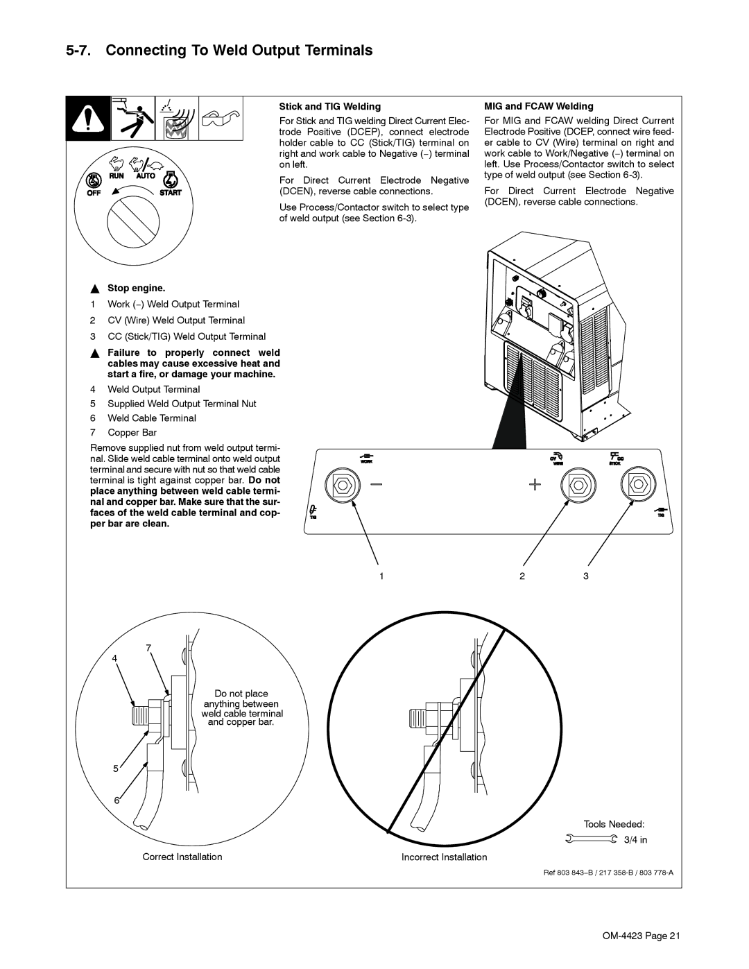
Stop engine
Connecting To Weld Output Terminals
Stick and TIG Welding
MIG and Fcaw Welding
Stop engine before
Selecting Weld Cable Sizes
150 ft 200 ft 250 ft
350 ft 400 ft 45 m 60 m 70 m 90 m 105 m 120 m
Socket
Connecting To Remote 14 Receptacle RC14
Stop
Front Panel Controls See Section
Description Of Front Panel Controls See Section
Process/Contactor Switch Settings
Process/Contactor Switch On CC/CV Models
Lift-Arc t TIG
Lift-ArcStart Procedure
Lift-Arc Start Method Touch
Do not Strike Like a Match
Remote Voltage/Amperage Control
Volt Receptacles
− Operating Auxiliary Equipment
Routine Maintenance
− Maintenance & Troubleshooting
Maintenance Label
Do not clean housing with air hose
Servicing Air Cleaner
By the warranty
To clean air filter
Inspecting And Cleaning Spark Arrestor Muffler
Stop engine and let cool. Reinstall cleanout plug
Servicing Engine Cooling System
Maximum
Adjusting Engine Speed On Standard Models
To replace primary canister fuel filter
Servicing Fuel And Lubrication Systems
Stop engine and let cool After servicing, start engine
To change oil and filter
Overload Protection
Press button to reset breaker
Replace Damaged Brushes
Checking Generator Brushes
Voltmeter/Ammeter Help Displays
Help 20 Display
Help 25 Display
Troubleshooting
Standard Generator Power
Welding
Engine
Check for obstructed throttle solenoid
Circuit Diagram For Welding Generator
− Electrical Diagrams
221 499-B
− RUN-IN Procedure
Wetstacking
Welding Generator
From flammables Do not Perform
Run-In Procedure Using Load Bank
Procedure at less than
Stop engine Do not touch hot exhaust
Do not perform run-in
Run-In Procedure Using Resistance Grid
Bank/grid
From flammables
− Generator Power Guidelines
Selecting Equipment
Grounding Generator To Truck Or Trailer Frame
Amperes x Volts = Watts
Grounding When Supplying Building Systems
How Much Power Does Equipment Require?
Earth ground if supplying
Farm/Home Equipment Rating Starting Watts Running Watts
Approximate Power Requirements For Industrial Motors
Approximate Power Requirements For Farm/Home Equipment
Industrial Motors Rating Starting Watts Running Watts
Contractor Rating Starting Watts Running Watts
Approximate Power Requirements For Contractor Equipment
KVA/HP x HP x 1000 = Starting Amperage
Power Required To Start Motor
How Much Power Can Generator Supply?
Single-Phase Induction Motor Starting Requirements
Typical Connections To Supply Standby Power
Current Load Watts Amperes
Selecting Extension Cord Use Shortest Cord Possible
103 − −5 104 − −3 96− −2 102 101 100
− Parts List
3031 5756
71− −4
Dia Part Description Quantity Mkgs
Dia Part Description Quantity
213600
Panel, Front w/Components -1Item
Panel, Front w/Components
FUEL/HM
Control Panel
Generator -1Item
Generator
Rectifier Assembly
Wiring Harnesses
Service
Your distributor also gives
Support
Your distributor and/or equipment manufacturer’s
To locate a Distributor or Service Agency visit
Miller Electric Mfg. Co
For assistance in filing or settling claims, contact