Standoff Support (3)
Contactor Control
Board PC3
![]() Wiring Harness Plug
Wiring Harness Plug
Voltage Control
Board PC4
Wiring Harness Plug
Standoff
Support (4)
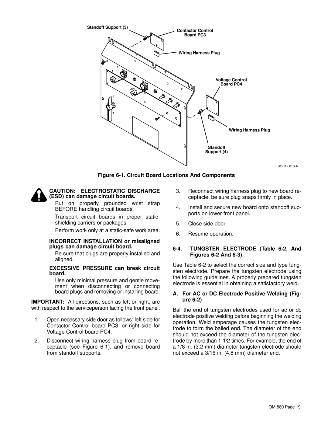
Figure 6-1. Circuit Board Locations And Components
CAUTION: ELECTROSTATIC DISCHARGE (ESD) can damage circuit boards.
•Put on properly grounded wrist strap BEFORE handling circuit boards.
•Transport circuit boards in proper static- shielding carriers or packages.
•Perform work only at a
INCORRECT INSTALLATION or misaligned plugs can damage circuit board.
•Be sure that plugs are properly installed and aligned.
EXCESSIVE PRESSURE can break circuit board.
•Use only minimal pressure and gentle move- ment when disconnecting or connecting board plugs and removing or installing board.
IMPORTANT: All directions, such as left or right, are with respect to the serviceperson facing the front panel.
1.Open necessary side door as follows: left side for Contactor Control board PC3, or right side for Voltage Control board PC4.
2.Disconnect wiring harness plug from board re- ceptacle (see Figure
3.Reconnect wiring harness plug to new board re- ceptacle; be sure plug snaps firmly in place.
4.Install and secure new board onto standoff sup- ports on lower front panel.
5.Close side door.
6.Resume operation.
6-4. TUNGSTEN ELECTRODE (Table 6-2, And Figures 6-2 And 6-3)
Use Table
A.For AC or DC Electrode Positive Welding (Fig- ure 6-2)
Ball the end of tungsten electrodes used for ac or dc electrode positive welding before beginning the welding operation. Weld amperage causes the tungsten elec- trode to form the balled end. The diameter of the end should not exceed the diameter of the tungsten elec- trode by more than
