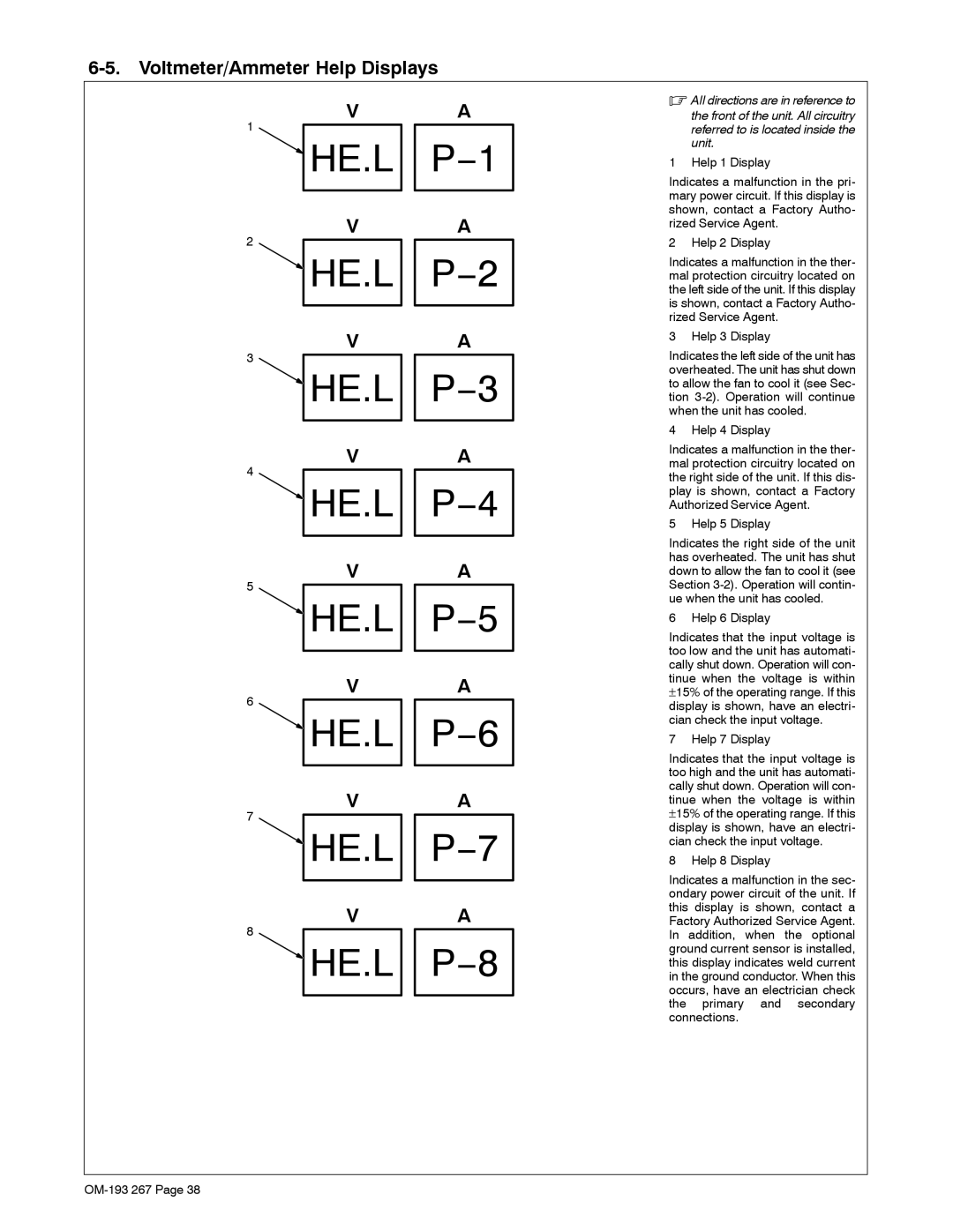
6-5. Voltmeter/Ammeter Help Displays
V A
1
HE.L P−1
V A
2
![]() HE.L P−2
HE.L P−2
V A
3
![]() HE.L P−3
HE.L P−3
V A
4
![]() HE.L P−4
HE.L P−4
V A
5
![]() HE.L P−5
HE.L P−5
V A
6
![]() HE.L P−6
HE.L P−6
V A
7
![]() HE.L P−7
HE.L P−7
V A
8
![]() HE.L P−8
HE.L P−8
.All directions are in reference to
the front of the unit. All circuitry referred to is located inside the unit.
1 Help 1 Display
Indicates a malfunction in the pri- mary power circuit. If this display is shown, contact a Factory Autho- rized Service Agent.
2 Help 2 Display
Indicates a malfunction in the ther- mal protection circuitry located on the left side of the unit. If this display is shown, contact a Factory Autho- rized Service Agent.
3 Help 3 Display
Indicates the left side of the unit has overheated. The unit has shut down to allow the fan to cool it (see Sec- tion
4 Help 4 Display
Indicates a malfunction in the ther- mal protection circuitry located on the right side of the unit. If this dis- play is shown, contact a Factory Authorized Service Agent.
5 Help 5 Display
Indicates the right side of the unit has overheated. The unit has shut down to allow the fan to cool it (see Section
6 Help 6 Display
Indicates that the input voltage is too low and the unit has automati- cally shut down. Operation will con- tinue when the voltage is within
±15% of the operating range. If this display is shown, have an electri- cian check the input voltage.
7 Help 7 Display
Indicates that the input voltage is too high and the unit has automati- cally shut down. Operation will con- tinue when the voltage is within
±15% of the operating range. If this display is shown, have an electri- cian check the input voltage.
8 Help 8 Display
Indicates a malfunction in the sec- ondary power circuit of the unit. If this display is shown, contact a Factory Authorized Service Agent. In addition, when the optional ground current sensor is installed, this display indicates weld current in the ground conductor. When this occurs, have an electrician check the primary and secondary connections.