| I N V I S | I O N 4 5 6 M P |
|
| |||||
| C O P Y R | I G H T | (C) 1 9 9 8 |
|
| ||||
| M I | L | L E R E l | e c t r i c |
|
| |||
| M f | g | C o X X X X X X |
|
| ||||
|
|
|
|
|
|
|
|
|
|
|
|
|
|
|
|
|
|
|
|
|
|
|
|
|
|
|
|
|
|
|
|
|
|
|
|
|
|
|
|
|
|
|
|
|
| 1 |
|
| |
|
|
|
|
|
|
|
|
|
|
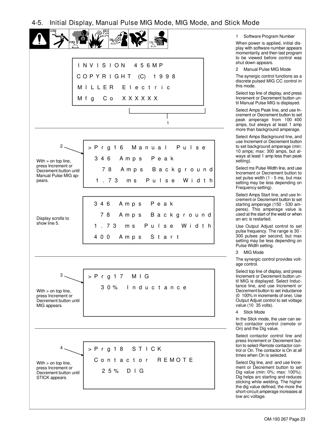
1 Software Program Number
When power is applied, initial dis- play with software number appears momentarily, and then last program to be viewed before control was shut down appears.
2 Manual Pulse MIG Mode
The synergic control functions as a discrete pulsed MIG CC control in this mode.
Select top line of display, and press Increment or Decrement button un- til Manual Pulse MIG is displayed.
Select Amps Peak line, and use In- crement or Decrement button to set peak amperage from 100−400 amps, but always at least 1 amp more than background amperage.
2
With > on top line, press Increment or Decrement button until Manual Pulse MIG ap- pears.
Display scrolls to show line 5.
| > P r | g 1 6 M a n u a l P u l s e | |||
| 3 4 6 A m p s P e a k | ||||
| 7 8 A m p s | B a c k g r o u n d | |||
| 1 . 7 3 | m s | P u l s e W i d t h | ||
|
|
|
| ||
|
|
|
| ||
| 3 4 6 |
| A m p s P e a k | ||
| 7 8 |
| A m p s | B a c k g r o u n d | |
| 1 . | 7 | 3 | m s | P u l s e W i d t h |
| 4 0 | 0 |
| A m p s | S t a r t |
|
|
|
|
|
|
Select Amps Background line, and use Increment or Decrement button to set background amperage (min: 10 amps; max: 300 amps, but al- ways at least 1 amp less than peak setting).
Select ms Pulse Width line, and use Increment or Decrement button to set pulse width (1 - 5 ms, but max setting may be less depending on Frequency setting).
Select Amps Start line, and use In- crement or Decrement button to set starting amperage (150 - 530 am- peres). This amperage value is used at the start of the weld or when an arc is restarted.
Use Output Adjust control to set pulse frequency. The range is 30 - 300 pulses per second, but max setting may be less depending on Pulse Width setting.
3 MIG Mode
The synergic control provides volt- age control.
3 | > P r | g 1 7 | M I G |
|
With > on top line, | 3 | 0 % | I n d u c t a n c e |
|
|
|
|
| |
press Increment or |
|
|
|
|
Decrement button until |
|
|
|
|
MIG appears. |
|
|
|
|
|
|
|
|
|
|
|
|
|
|
4 | > P r g 1 8 S T I C K |
With > on top line, | C o n t a c t o r R E M O T E |
| |
press Increment or | 2 5 % D I G |
Decrement button until | |
STICK appears. |
|
|
|
Select top line of display, and press Increment or Decrement button un- til MIG is displayed. Select Induc- tance line, and use Increment or Decrement button to set inductance (0−100% in increments of one). Use Output Adjust control to set voltage value (10−35 volts).
4 Stick Mode
In the Stick mode, the user can se- lect contactor control (remote or On) and the Dig value.
Select contactor control line and press Increment or Decrement but- ton to select Remote contactor con- trol or On. The contactor is On at all times when On is selected.
Select Dig line, and and use Incre- ment or Decrement button to set Dig value (min: 0%; max: 100%). Dig helps arc starting and reduces sticking while welding. The higher the dig value defined, the more the
