Description
Processes
File Engine Drive
Visit our website at OM-494191 862Q September
From Miller to You
Table of Contents
− Operating Auxiliary Equipment
Arc Welding Hazards
Symbol Usage
Engine Hazards
Compressed Air Hazards
California Proposition 65 Warnings
Principal Safety Standards
EMF Information
Radiation can cause interference
− Consignes DE Sécurité − Lire Avant Utilisation
Signification des symboles
UN Choc Électrique peut tuer
LES Fumées ET LES GAZ peuvent être dangereux
DES Particules Volantes peuvent blesser les yeux
LE Soudage peut provoquer un in- cendie ou une explosion
DES Pièces Chaudes peuvent provoquer des brûlures graves
LE Bruit peut affecter l’ouïe
’AIR Comprimé peut provoquer des blessures
LA Chaleur DU Moteur peut pro- voquer un incendie
’EMPLOI Excessif peut
LE Surchauffement peut endom- mager le moteur électrique
Pour les moteurs à essence
LE Soudage À L’ARC risque de provoquer des interférences
Pour les moteurs diesel
Boulevard, Rexdale, Ontario, Canada M9W 1R3 téléphone
− Definitions
Symbols And Definitions
Weld, Power, And Engine Specifications
− Specifications
Dimensions, Weights, And Operating Angles
Description
Fuel Consumption
AC Generator Power
Duty Cycle And Overheating
Exceeding duty cycle can damage unit and void warranty
Overheating
Reduce Duty Cycle Minutes
CC/DC − Dual Mode
CC/DC − Single Mode
CV/DC Mode
Volt-Ampere Curves
Installing Welding Generator
− Installation
Connecting The Battery
Activating The Dry Charge Battery If Applicable
Do not overfill battery cells
For 30 Minutes
Engine Prestart Checks
Installing Exhaust Pipe
Stop engine and let cool
Fuel
Weld Output Terminals
Safety Information For Connecting To Weld Output Terminals
Unexpected Weld Output can cause injury or fire
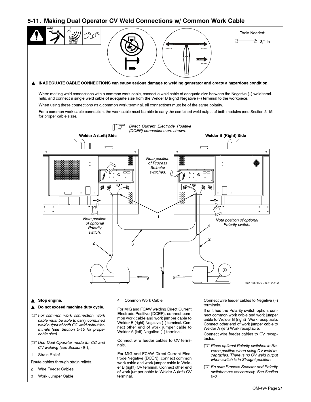
Welder a Left Side Welder B Right Side
Do not exceed machine duty cycle
Welder a Left Side
Connect electrode holder cables to Elec- trode receptacles
Stop engine Do not exceed machine duty cycle
Verse position when using CV weld re
Place optional Polarity switches in Re
When switch is in Straight position
Switches are set correctly. See Section
Connect wire feeder cables to CV recep- tacles
Connect wire feeder cables to Negative − terminals
Be sure Process Selector switches are
Place optional Polarity switch in Re
Making Single Operator CC Weld Connections
OM-494
150 ft 200 ft 250 ft
Selecting Weld Cable Sizes
350 ft 400 ft 45 m 60 m 70 m 90 m 105 m 120 m
Put terminals
After installing cylinder, wait at
Installing Ether Cylinder Optional Ether Starting Aid
Remote 14 Receptacle Information
Socket Information
Dual Operator Operation
Remote 14 Receptacle Connections
Engine Controls
− Operating the Welding Generator
See -3for weld control descriptions
If light goes on, stop engine and check engine belt
Weld Controls See Section
Do not switch under load
Do not switch under load or with out- put on
Weld Control Descriptions See Section
CV weld output for MIG is only available
− Operating Auxiliary Equipment
Generator power is not affected by weld output
Volt And 240 Volt Duplex Receptacles
At least once a month, run engine at
Routine Maintenance
− Maintenance & Troubleshooting
Maintenance Label
By the warranty
Servicing Air Cleaner
To clean air filter
Do not clean housing with air hose
Servicing Fuel And Lubrication Systems
Weld/Power
Adjusting Engine Speed
Servicing Optional Ether Starting Aid
Cylinder
Checking And Replacing Alternator Belt
To adjust belt tension
Max Tools Needed 11/16
Stop engine To check belt tension
Resetting Fan Belt Safety Shutdown
Stop engine and let cool. Reinstall cleanout plug
Inspecting And Cleaning Optional Spark Arrestor Muffler
Checking Generator Brushes
Thermostats TP3 And TP4 Internal − Not Shown
Circuit Protection
Welding
Troubleshooting
Factory Authorized Service Agent check main rectifier SR3
Factory Authorized Service Agent check main rectifier SR2
Repair or replace wire feeder
Formers T5 thru T10, and control board PC1 or PC5
Engine
Generator Power
OM-494
Circuit Diagram For Welding Generator
− Electrical Diagrams
210 657-A
Wetstacking
− RUN-IN Procedure
Ment damage may occur
4exceed duty cycle or equip- ment damage may occur
Run-In Procedure Using Load Bank
Check oil level frequently dur
Ing run-in add oil if needed
Procedure at less than
Run-In Procedure Using Resistance Grid
Bank/grid
From flammables
Has this symbol
− Generator Power Guidelines
Selecting Equipment
Grounding Generator To Truck Or Trailer Frame
How Much Power Does Equipment Require?
Grounding When Supplying Building Systems
Earth ground if supplying
Use ground device as stated Electrical codes
Approximate Power Requirements For Farm/Home Equipment
Approximate Power Requirements For Industrial Motors
Industrial Motors Rating Starting Watts Running Watts
Farm/Home Equipment Rating Starting Watts Running Watts
Contractor Rating Starting Watts Running Watts
Approximate Power Requirements For Contractor Equipment
How Much Power Can Generator Supply?
Power Required To Start Motor
Single-Phase Induction Motor Starting Requirements
KVA/HP x HP x 1000 = Starting Amperage
Typical Connections To Supply Standby Power
Current Load Watts Amperes
Selecting Extension Cord Use Shortest Cord Possible
96−SEE FIG 92 91 103 102 101 100 25−SEE FIG 910
− Parts List
4748 57−SEE FIG 78−SEE FIG 76 75
Item Dia Part Description Quantity Mkgs
189
Front Panel
Front Panel -1Item
Side Control Panels − Welder B Right Side Shown
Side Control Panels -1Item
Side Control Panels
Generator
Rectifier Assembly
OM-494
Page
Your distributor also gives
Service
Support
Miller Electric Mfg. Co
To locate a Distributor or Service Agency visit
For assistance in filing or settling claims, contact
Your distributor and/or equipment manufacturer’s