5
3
4 ![]()
.The interconnecting power
cord is not supplied with the unit. Be sure to obtain the prop- er interconnecting power cord for the welding power source the wire feeder is being con- nected to.
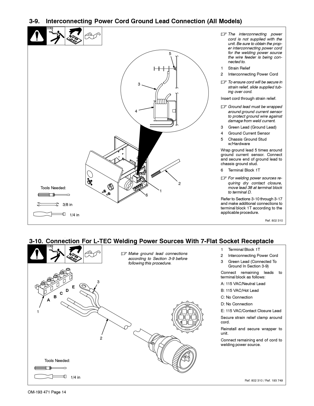
1Strain Relief
2Interconnecting Power Cord
.To ensure cord will be secure in
strain relief, slide supplied tub- ing over cord.
Insert cord through strain relief.
.Ground lead must be wrapped
around ground current sensor to protect ground wire against damage from weld current.
3Green Lead (Ground Lead)
4Ground Current Sensor
5Chassis Ground Stud w/Hardware
Wrap ground lead 5 times around ground current sensor. Connect and secure end of ground lead to chassis ground stud.
6 Terminal Block 1T
Tools Needed:
2
1
. For welding power sources re- |
quiring dry contact closure, |
move lead 38 at terminal block |
to terminal D. |
6
3/8 in
1/4 in
Refer to Sections
Ref. 802 310
|
|
| . Make ground lead connections |
| 1 | Terminal Block 1T |
|
| |
|
|
|
| 2 | Interconnecting Power Cord |
| |||
|
|
| according to Section |
|
| ||||
|
|
|
| 3 Green Lead (Connected To |
| ||||
|
|
| following this procedure. |
|
| ||||
|
|
|
|
| Ground In Section |
| |||
|
|
|
|
|
|
| |||
|
|
|
|
| Connect | remaining | leads | to | |
|
|
| 3 |
| terminal block as follows: |
| |||
|
|
|
| A: 115 VAC/Neutral Lead |
| ||||
|
|
| E |
|
| ||||
| B | C D |
| B: 115 VAC/Hot Lead |
|
| |||
A |
|
|
| C: No Connection |
|
| |||
|
|
|
|
| D: No Connection |
|
| ||
1 |
|
| 1 | 2 | E: 115 VAC/Contact Closure Lead | ||||
|
| 3 | 5 | ||||||
|
|
| Secure strain relief clamp around | ||||||
|
|
|
|
| |||||
|
|
| 6 | 7 | cord. |
|
|
| |
|
|
|
|
| Reinstall and secure wrapper to | ||||
|
|
| 2 |
| unit. |
|
|
| |
|
|
|
| Connect remaining end of cord to | |||||
|
|
|
|
| |||||
|
|
|
|
| welding power source. |
|
| ||
Tools Needed: |
|
|
|
|
|
|
| ||
|
|
| 1/4 in |
|
|
| Ref. 802 310 / Ref. 193 749 | ||
|
|
|
|
|
|
| |||
|
|
|
|
|
|
|
| ||
