4-12. Installing PD Continuous Wire Guides
3
1 | 2 | 4 |
|
|
Ref. 804
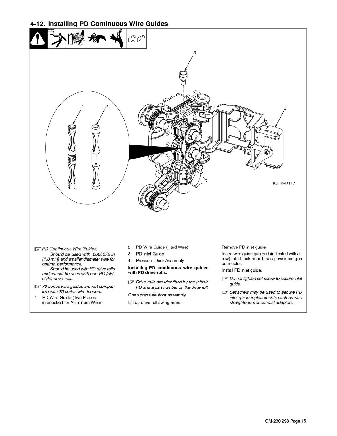
.PD Continuous Wire Guides:
Should be used with .068/.072 in
(1.8 mm) and smaller diameter wire for optimal performance.
Should be used with PD drive rolls and cannot be used with
.70 series wire guides are not compat- ible with 75 series wire feeders.
1PD Wire Guide (Two Pieces interlocked for Aluminum Wire)
2PD Wire Guide (Hard Wire)
3PD Inlet Guide
4Pressure Door Assembly
Installing PD continuous wire guides with PD drive rolls.
.Drive rolls are identified by the initials PD and a part number on the drive roll.
Open pressure door assembly.
Lift up drive roll swing arms.
Remove PD inlet guide.
Insert wire guide gun end (indicated with ar- row) into block near brass power pin gun connector.
Install PD inlet guide.
.Do not tighten set screw to secure inlet guide.
.Set screw may be used to secure PD
inlet guide replacements such as wire straighteners or conduit adapters.