4-4. Installing Wire Guide Extension
1 |
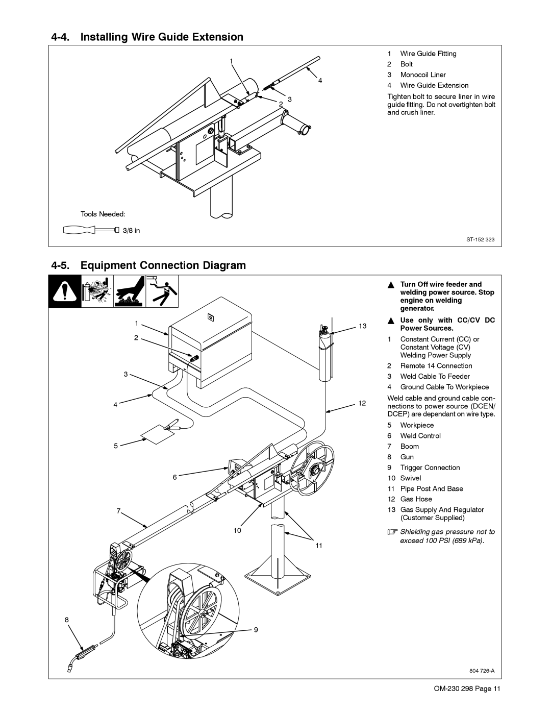
| 1 | Wire Guide Fitting |
| 2 | Bolt | |
|
| ||
| 4 | 3 | Monocoil Liner |
| 4 | Wire Guide Extension | |
|
| ||
2 3 |
| Tighten bolt to secure liner in wire | |
| guide fitting. Do not overtighten bolt | ||
and crush liner.
Tools Needed:
![]() 3/8 in
3/8 in
4-5. Equipment Connection Diagram
1
2
3
4 ![]()
5 ![]()
6 ![]()
7
10
YTurn Off wire feeder and welding power source. Stop engine on welding generator.
YUse only with CC/CV DC
13 | Power Sources. |
1Constant Current (CC) or Constant Voltage (CV) Welding Power Supply
2Remote 14 Connection
3Weld Cable To Feeder
4Ground Cable To Workpiece
12 | Weld cable and ground cable con- | ||
nections to power source (DCEN/ | |||
| |||
| DCEP) are dependant on wire type. | ||
| 5 | Workpiece | |
| 6 | Weld Control | |
| 7 | Boom | |
| 8 | Gun | |
| 9 | Trigger Connection | |
| 10 | Swivel | |
| 11 | Pipe Post And Base | |
| 12 | Gas Hose | |
| 13 | Gas Supply And Regulator | |
|
| (Customer Supplied) | |
| . Shielding gas pressure not to |
11 | exceed 100 PSI (689 kPa). |
|
8
9
804