7.Attach the power cord to the switcher and to the AC power source. Ensure the switcher is working properly.
8.If the switcher was removed from a rack, remove its power cord, reattach the switcher to the rack, and reconnect the power cord.
9. | Reconnect the input and output cables. |
Installing a firmware update
The IC that contains the firmware for the matrix switcher also contains the memory in which presets and audio levels are saved. When you replace the IC, these settings will be lost. You may want to record the presets and audio levels before you replace the IC.
To replace the firmware, do the following:
1.Follow the appropriate instructions in Opening the Switcher on page
2.Locate the
CAUTION
Do not touch the components inside the switcher without being electrically grounded. Electrostatic discharge (ESD) can damage ICs, even if you cannot feel, see, or hear it.
3.Unplug the power cable from the front panel board.
4.Place the front panel board, button side down, on a suitable workspace.
5.Locate IC U7 (figure
6.Use the PLCC IC puller to remove the existing firmware IC. Squeeze the tool to align its hooks with the slots in opposite corners of socket U7. Insert the hooks, squeeze gently, and pull the IC straight out of the socket. Set the IC aside.
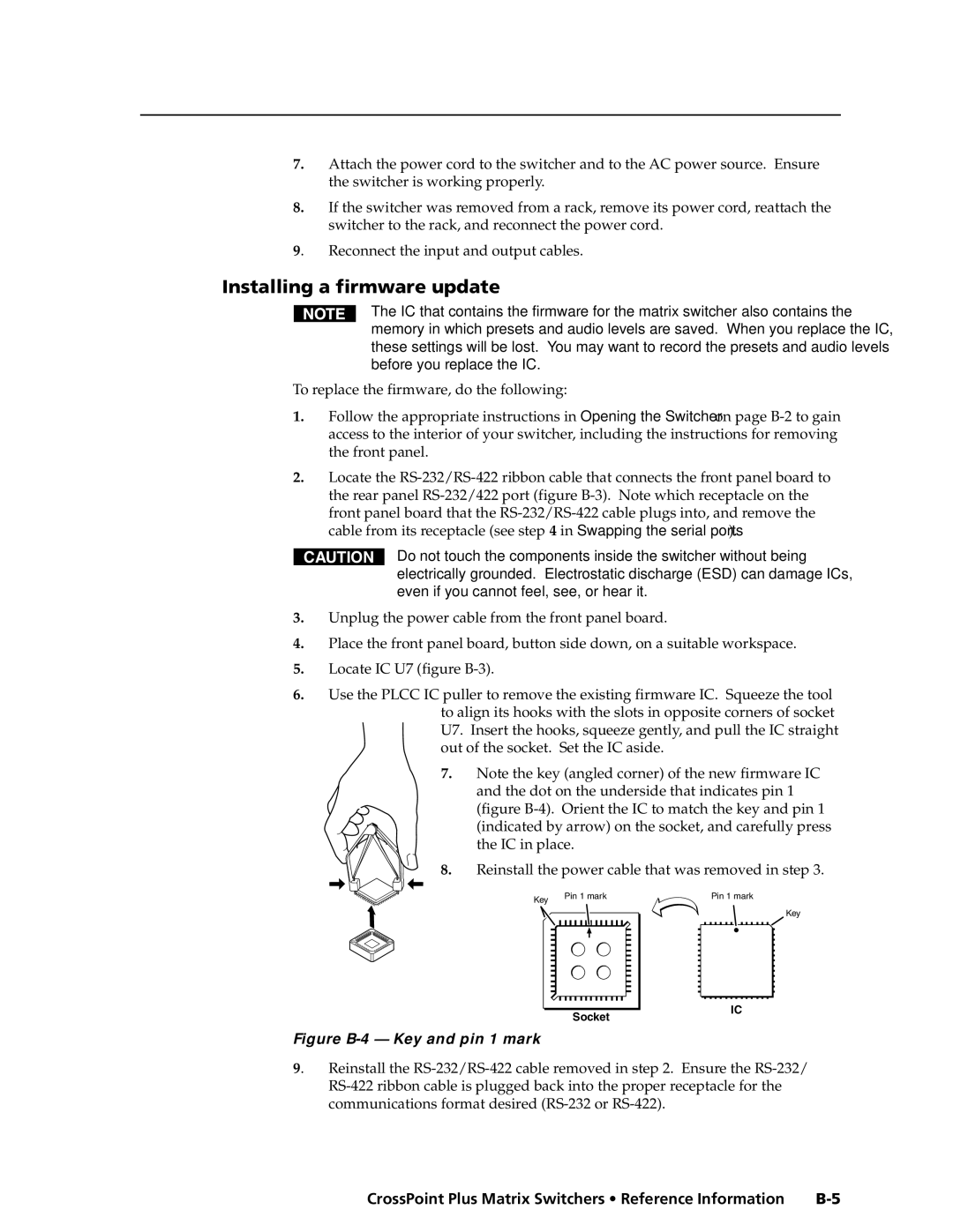
7.Note the key (angled corner) of the new firmware IC and the dot on the underside that indicates pin 1
(figure B-4). Orient the IC to match the key and pin 1 (indicated by arrow) on the socket, and carefully press the IC in place.
8.Reinstall the power cable that was removed in step 3.
Key | Pin 1 mark |
Socket |
Pin 1 mark
Key
IC |
Figure B-4 — Key and pin 1 mark
9. Reinstall the
CrossPoint Plus Matrix Switchers • Reference Information |