Reference Information, cont’d
Closing the switcher
1. | Reinstall any cables removed. To plug a self latching cable into the desired | |||
| Ribbon cable | receptacle, align the holes in the connector with the pins in the | ||
|
|
| receptacle, and press evenly until the receptacle tabs lock into | |
|
|
| place. | |
| ||||
2. | Place the top cover (CrossPoint Plus 84, 88, 124, and 128) and/or front cover | |||
| (all models) in place and replace all the screws removed in Opening the | |||
| switcher on page | |||
Swapping the serial ports
The CrossPoint Plus switchers are factory configured for
1.Follow the appropriate instructions in Opening the Switcher on page
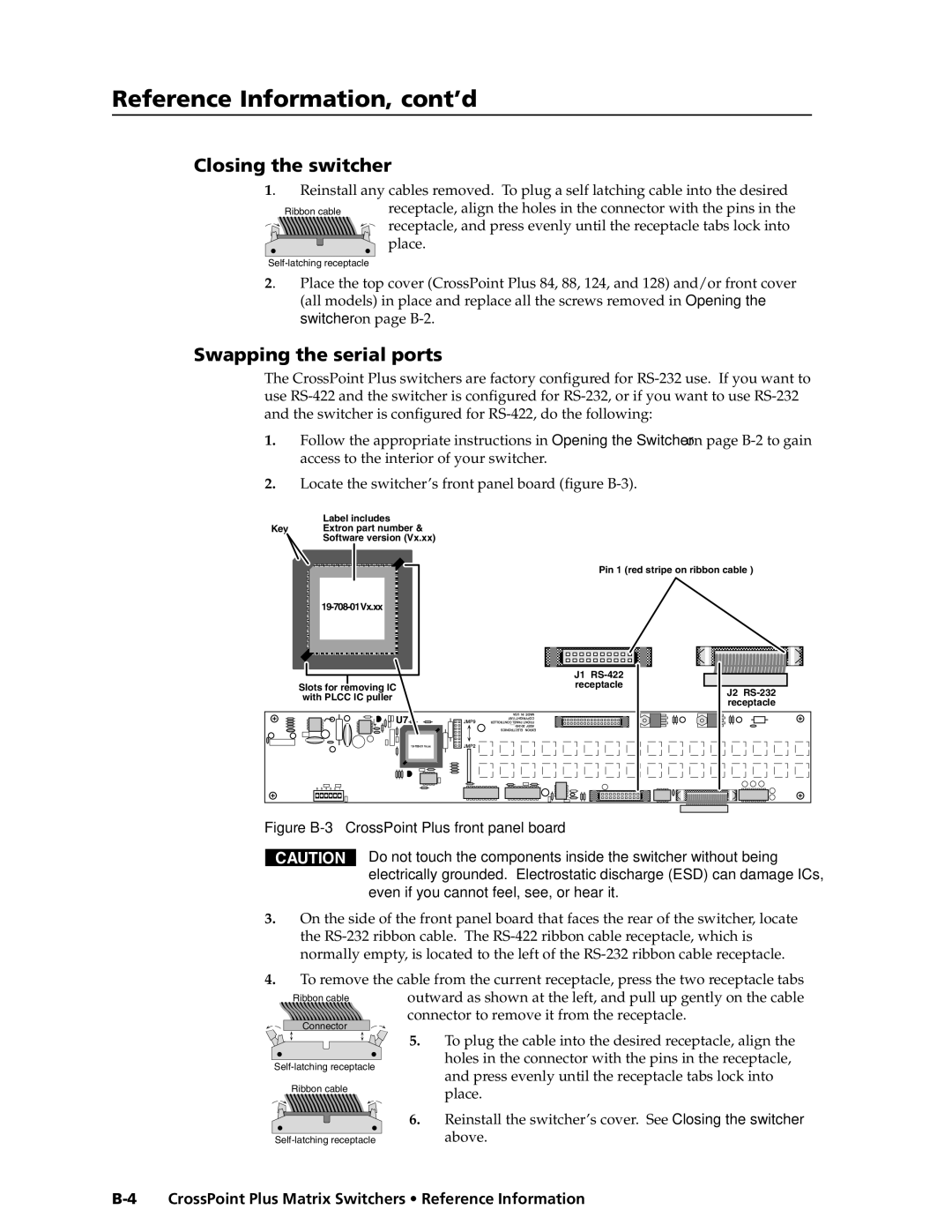
2.Locate the switcher’s front panel board (figure
Label includes
Key Extron part number &
Software version (Vx.xx)
| Pin 1 (red stripe on ribbon cable ) | |
| ||
| J1 | |
Slots for removing IC | receptacle | |
J2 | ||
with PLCC IC puller | ||
receptacle | ||
| ||
U7 |
|
Figure B-3 — CrossPoint Plus front panel board
CAUTION
Do not touch the components inside the switcher without being electrically grounded. Electrostatic discharge (ESD) can damage ICs, even if you cannot feel, see, or hear it.
3.On the side of the front panel board that faces the rear of the switcher, locate the
4.
