Installation, cont’d
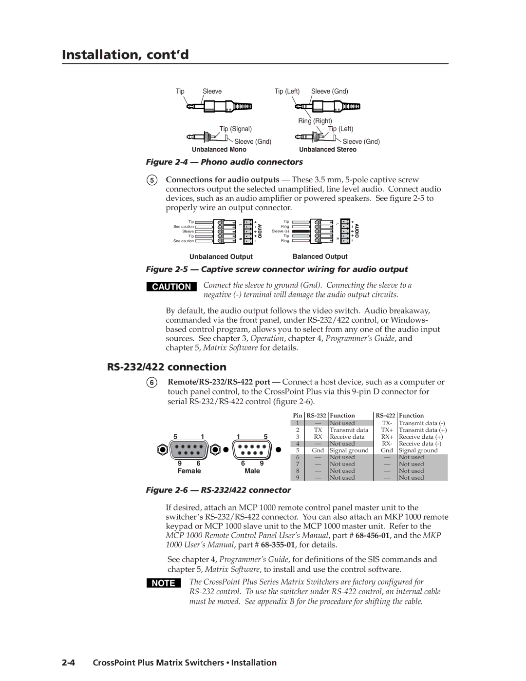
Tip | Sleeve | Tip (Left) | Sleeve (Gnd) |
|
| Ring (Right) | |
| Tip (Signal) |
| Tip (Left) |
| Sleeve (Gnd) |
| Sleeve (Gnd) |
| Unbalanced Mono | Unbalanced Stereo | |
Figure 2-4 — Phono audio connectors
5Connections for audio outputs — These 3.5 mm,
Tip ![]() See caution
See caution ![]() Sleeve
Sleeve ![]() Tip
Tip ![]()
See caution ![]()
Tip
Ring
Sleeve (s)
Tip
Ring
Unbalanced Output | Balanced Output |
Figure 2-5 — Captive screw connector wiring for audio output
CAUTION
Connect the sleeve to ground (Gnd). Connecting the sleeve to a negative
By default, the audio output follows the video switch. Audio breakaway, commanded via the front panel, under
RS-232/422 connection
6
5 | 1 | 1 | 5 |
9 | 6 | 6 | 9 |
Female | Male | ||
Pin |
| Function |
| Function |
1 | — | Not used | TX- | Transmit data |
2 | TX | Transmit data | TX+ | Transmit data (+) |
3 | RX | Receive data | RX+ | Receive data (+) |
4 | — | Not used | RX- | Receive data |
5 | Gnd | Signal ground | Gnd | Signal ground |
6 | — | Not used | — | Not used |
7 | — | Not used | — | Not used |
8 | — | Not used | — | Not used |
9 | — | Not used | — | Not used |
Figure 2-6 — RS-232/422 connector
If desired, attach an MCP 1000 remote control panel master unit to the switcher’s
See chapter 4, Programmer’s Guide, for definitions of the SIS commands and chapter 5, Matrix Software, to install and use the control software.
The CrossPoint Plus Series Matrix Switchers are factory configured for