Access to the bearings and seals for lubrication is provided by the various grease passages. Excess lubricant is excreted through the bearing and seal cavity
If bearing replacement becomes necessary due to wear, it is essential that the bearings and seals are replaced. Seal replacement requires removal of the bearing housing and seal sleeve. (In rare instances where the seals are known to be in good condition, it is not necessary to remove the bearing housing, seals or seal sleeve when a bearing is replaced.) A pulling fixture is required to remove the bearing housing. A set of guide rods, a seal sleeve setting fixture and a bearing setting fixture are required for reinstallation of the housing. These tools are available for rental or purchase from the Milnor® factory and are pictured elsewhere in this section. Contact the factory two weeks in advance of repairs, when ordering these tools.
This maintenance is performed in the following order:
1.Remove old bearing(s). When removing both bearings, remove the front (soil side) bearing first.
2.Remove bearing housings, seal sleeves, and seals.
3.If both bearings were removed, install the bearing housing, seal sleeve, seals, and new bearing on the rear (clean side).
4.Install the bearing housing, seal sleeve, seals, and new bearing on the front (soil side).
5.Tighten bearing(s).
See the Main Bearing Assembly drawing for your machine for bearing component part numbers.
Removing the Bearing (Front or Rear)
1.Loosen, then remove the main drive belts and cylinder shaft pulley (if applicable) by lowering the drive base with the jacking bolts. Do not attempt to pry belts off with a pry bar or by rolling the sheave. Remove the bearing cover (or shaft seal holder) to expose the bearing.
2.Bend back the locking tang on the bearing lock- washer then remove the locknut and lockwasher.
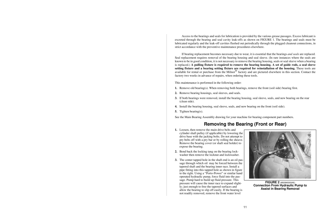
3.The center tapped hole in the shaft end is an oil pas- sage through which oil may be forced between the tapered shaft and the bearing inner race. Install a pipe fitting into this tapped hole as shown in figure to the right. Using a
FIGURE 2 (MSSM0303AE)
Connection From Hydraulic Pump to
Assist in Bearing Removal
11
