Tightening Bearing(s) (Front and/or Rear)
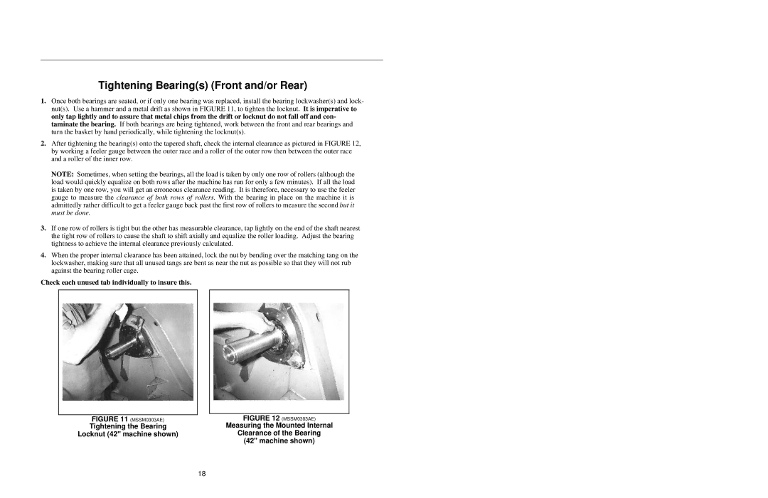
1.Once both bearings are seated, or if only one bearing was replaced, install the bearing lockwasher(s) and lock- nut(s). Use a hammer and a metal drift as shown in FIGURE 11, to tighten the locknut. It is imperative to only tap lightly and to assure that metal chips from the drift or locknut do not fall off and con- taminate the bearing. If both bearings are being tightened, work between the front and rear bearings and turn the basket by hand periodically, while tightening the locknut(s).
2.After tightening the bearing(s) onto the tapered shaft, check the internal clearance as pictured in FIGURE 12, by working a feeler gauge between the outer race and a roller of the outer row then between the outer race and a roller of the inner row.
NOTE: Sometimes, when setting the bearings, all the load is taken by only one row of rollers (although the load would quickly equalize on both rows after the machine has run for only a few minutes). If all the load is taken by one row, you will get an erroneous clearance reading. It is therefore, necessary to use the feeler gauge to measure the clearance of both rows of rollers. With the bearing in place on the machine it is admittedly rather difficult to get a feeler gauge back past the first row of rollers to measure the second but it must be done.
3.If one row of rollers is tight but the other has measurable clearance, tap lightly on the end of the shaft nearest the tight row of rollers to cause the shaft to shift axially and equalize the roller loading. Adjust the bearing tightness to achieve the internal clearance previously calculated.
4.When the proper internal clearance has been attained, lock the nut by bending over the matching tang on the lockwasher, making sure that all unused tangs are bent as near the nut as possible so that they will not rub against the bearing roller cage.
Check each unused tab individually to insure this.
|
|
|
|
| FIGURE 12 (MSSM0303AE) |
FIGURE 11 (MSSM0303AE) |
| |
Tightening the Bearing |
| Measuring the Mounted Internal |
Locknut (42" machine shown) |
| Clearance of the Bearing |
|
| (42" machine shown) |
18