•Do not operate the power tool near flammable materials. Sparks could ignite these materials.
•Do not use accessories that require liquid coolants. Using water or other liquid coolants may result in electrocution or shock.
Kickback and Related Warnings
Kickback is a sudden reaction to a pinched or snagged rotating wheel, sanding band, brush or any other accessory. Pinching or snagging causes rapid stalling of the rotating accessory which in turn causes the uncontrolled power tool to be forced in the direction opposite of the accessory’s rotation at the point of the binding.
For example, if an abrasive wheel is snagged or pinched by the workpiece, the edge of the wheel that is entering into the pinch point can dig into the surface of the material causing the wheel to climb out or kick out. The wheel may either jump toward or away from the operator, depending on direction of the wheel’s movement at the point of pinching. Abrasive wheels may also break under these conditions. Kickback is the result of power tool misuse and/or incorrect operating procedures or conditions and can be avoided by taking proper precautions as given below.
•Maintain a firm grip on the power tool and position your body and arm to allow you to resist kickback forces. The operator can control kickback forces, if proper precautions are taken.
•Use special care when working corners, sharp edges etc. Avoid bouncing and snagging the accessory. Corners, sharp edges or bouncing have a tendency to snag the rotating accessory and cause loss of control or kickback.
•Do not attach a thin toothed saw blade. Such blades create frequent kickback and loss of control.
•Always feed the bit into the material in the same direction as the cutting edge is exiting from the material (which is the same direction as the chips are thrown). Feeding the tool in the wrong direction causes the cutting edge of the bit to climb out of the work and pull the tool in the direction of this feed.
•When using steel saws, cut-off wheels, high- speed cutters or tungsten carbide cutters, always have the work securely clamped. These wheels will grab if they become slightly canted in the groove, and can kickback. When a cut-off wheel grabs, the wheel itself usually breaks. When the steel saw, high-speed cutters or tungsten carbide cutter grab, it may jump from the groove and you could lose control of the tool.
Safety Warnings Specific for Grinding and Abrasive Cutting-Off Operations:
•Use only wheel types that are recommended for your power tool and only for recommended applications. For example: do not grind with the side of a cut-off wheel. Abrasive cut-off wheels are intended for peripheral grinding, side forces applied to these wheels may cause them to shatter.
•For threaded abrasive cones and plugs use only undamaged wheel mandrels with an unrelieved shoulder flange that are of correct size and length. Proper mandrels will reduce the possibility of breakage.
•Do not “jam” a cut-off wheel or apply excessive pressure. Do not attempt to make an excessive depth of cut. Overstressing the wheel increases the loading and susceptibility to twisting or bind- ing of the wheel in the cut and the possibility of kickback or wheel breakage.
•Do not position your hand in line with and behind the rotating wheel. When the wheel, at the point of operation, is moving away from your hand, the possible kickback may propel the spin- ning wheel and the power tool directly at you.
•When wheel is binding or when interrupting a cut for any reason, switch off the power tool and hold the power tool motionless until the wheel comes to a complete stop. Never attempt to remove the cut-off wheel from the cut while the wheel is in motion otherwise kickback may occur. Investigate and take corrective action to eliminate the cause of wheel binding.
•Do not restart the cutting operation in the workpiece. Let the wheel reach full speed and carefully reenter the cut. The wheel may bind, walk up or kickback if the power tool is restarted in the workpiece.
•Support panels or any oversized workpiece to minimize the risk of wheel pinching and kick- back. Large workpieces tend to sag under their own weight. Supports must be placed under the workpiece near the line of cut and near the edge of the workpiece on both sides of the wheel.
•Use extra caution when making a “pocket cut” into existing walls or other blind areas. The pro- truding wheel may cut gas or water pipes, electrical wiring or objects that can cause kickback.
Safety Warnings Specific for Wire Brushing Operations:
•Be aware that wire bristles are thrown by the brush even during ordinary operation. Do not overstress the wires by applying excessive load to the brush. The wire bristles can easily penetrate light clothing and/or skin.
•Allow brushes to run at operating speed for at least one minute before using them. During this time no one is to stand in front or in line with the brush. Loose bristles or wires will be discharged during the run-in time.
•Direct the discharge of the spinning wire brush away from you. Small particles and tiny wire fragments may be discharged at high velocity during the use of these brushes and may become imbedded in your skin.
Additional Safety Warnings
•Maintain labels and nameplates. These carry important information. If unreadable or missing, contact a MILWAUKEE service facility for a free replacement.
•WARNING: Some dust created by power sanding, sawing, grinding, drilling, and other construction activities contains chemicals known to cause cancer, birth defects or other reproductive harm. Some examples of these chemicals are:
•lead from lead-based paint
•crystalline silica from bricks and cement and other masonry products, and
•arsenic and chromium from chemically-treated lumber.
Your risk from these exposures varies, depending on how often you do this type of work. To reduce your exposure to these chemicals: work in a well ventilated area, and work with approved safety equipment, such as those dust masks that are spe- cially designed to filter out microscopic particles.
SPECIFICATIONS
Max.
VoltsAccessory Cat. No. DC No load RPM Collet Diameter
2460-2012 5000 - 32000 1/8" * | 2" |
* accepts standard collet sizes 1/32", 1/16", 3/32", 1/8"
SYMBOLOGY
Direct Current
Underwriters Laboratories, Inc.
United States and Canada
No Load Revolutions per
Minute (RPM)
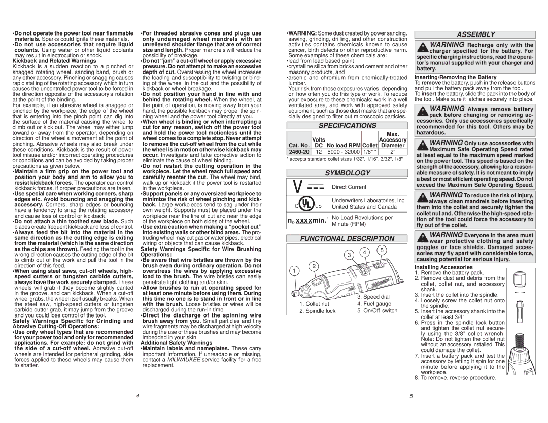
FUNCTIONAL DESCRIPTION
| | 3 | 4 | 5 |
| | |
| | | |
1 | 2 | | | |
| | | |
| | 3. | Speed dial |
1. | Collet nut | 4. | Fuel gauge |
2. | Spindle lock | 5. | On/Off switch |
ASSEMBLY
WARNING Recharge only with the charger specified for the battery. For specific charging instructions, read the opera- tor’s manual supplied with your charger and
battery.
Inserting/Removing the Battery
To remove the battery, push in the release buttons and pull the battery pack away from the tool.
To insert the battery, slide the pack into the body of the tool. Make sure it latches securely into place.
WARNING Always remove battery pack before changing or removing ac- cessories. Only use accessories specifically recommended for this tool. Others may be
hazardous.
WARNING Only use accessories with Maximum Safe Operating Speed rated at least equal to the maximum speed marked
on the power tool. This speed is based on the strength of the accessory, allowing for a reason- able measure of safety. It is not meant to imply a best or most efficient operating speed. Do not exceed the Maximum Safe Operating Speed.
WARNING To reduce the risk of injury, always clean mandrels before inserting them into the collet and securely tighten the collet nut and. Otherwise the high-speed rota- tion of the tool could force the accessory to
fly out of the collet.
WARNING Everyone in the area must wear protective clothing and safety goggles or face shields. Damaged acces- sories may fly apart with considerable force,
causing potential for serious injury.
Installing Accessories
1.Remove the battery pack.
2.Remove dust and debris from the collet, collet nut, and accessory shank.
3.Insert the collet into the spindle.
4.Loosely screw the collet nut onto the spindle.
5.Insert the accessory shank into the collet at least 3/4".
6.Press in the spindle lock button and tighten the collet nut secure-
ly using the 3/8" collet wrench. Note: Do not tighten the collet nut without an accessory installed. This could damage the collet.
7.Insert a battery pack and test the 


 accessory by letting it spin for one


 minute before applying it to the
 workpiece.
8.To remove, reverse procedure.