USER GUIDE
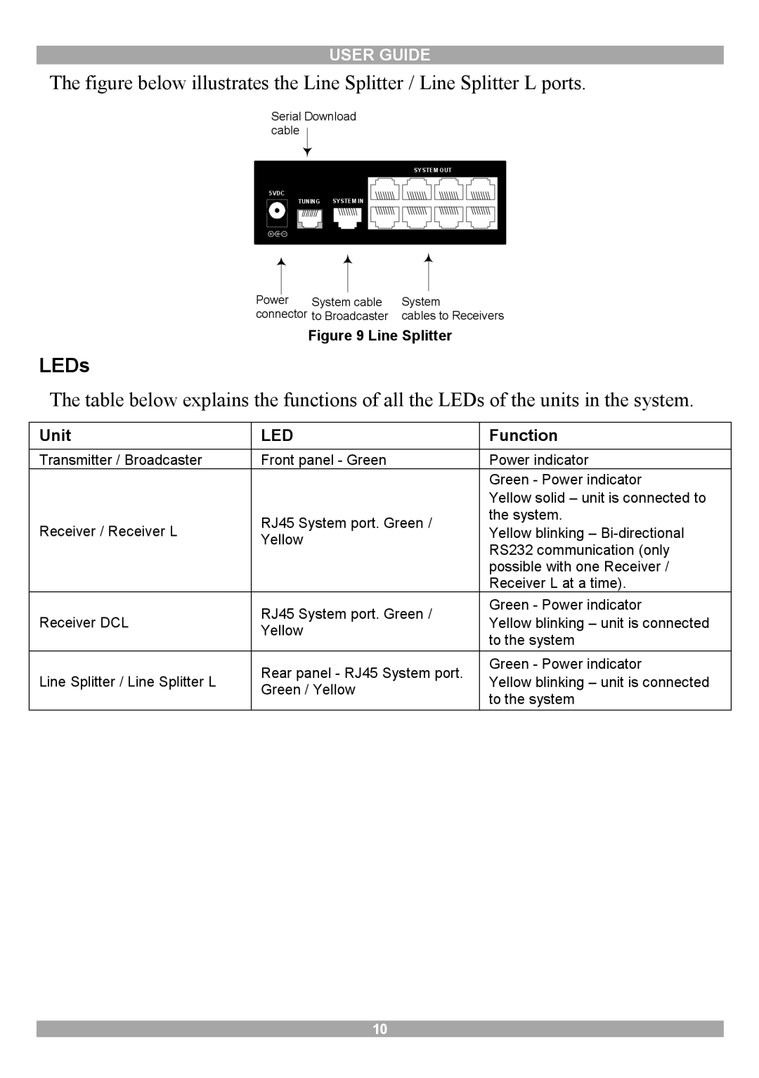
The figure below illustrates the Line Splitter / Line Splitter L ports.
Serial Download cable
| SYSTEM OUT |
5VDC |
|
TUNING | SYSTEM IN |
Power |
|
|
|
|
|
|
|
| |
System cable | System | |||
connector to Broadcaster | cables to Receivers | |||
Figure 9 Line Splitter
LEDs
The table below explains the functions of all the LEDs of the units in the system.
Unit | LED | Function | |
Transmitter / Broadcaster | Front panel - Green | Power indicator | |
|
| Green - Power indicator | |
|
| Yellow solid – unit is connected to | |
Receiver / Receiver L | RJ45 System port. Green / | the system. | |
Yellow blinking – | |||
Yellow | |||
| RS232 communication (only | ||
|
| ||
|
| possible with one Receiver / | |
|
| Receiver L at a time). | |
Receiver DCL | RJ45 System port. Green / | Green - Power indicator | |
Yellow blinking – unit is connected | |||
Yellow | |||
| to the system | ||
|
| ||
Line Splitter / Line Splitter L | Rear panel - RJ45 System port. | Green - Power indicator | |
Yellow blinking – unit is connected | |||
Green / Yellow | |||
| to the system | ||
|
|
10